SPECIFICATIONS
Part No.: IS220PPROH1AG
Manufacturer: General Electric
Country of Manufacture: United States of America (USA)
Output Fuses: 12 fuses, two per output, 250 V, 15 A
Temperature: -30 to +65oC
Size: 23.495 cm high x 10.795 cm wide
Mounting: DIN-rail
Product Type: Emergency Protection I/O pack
Availability: In Stock
Series: Mark VIe
Functional Description
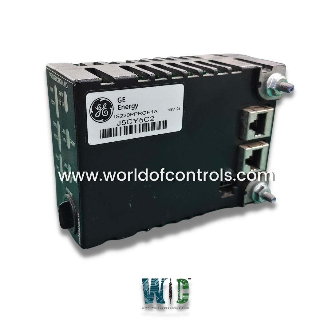
IS220PPROH1AG is an emergency protection I/O pack developed by GE. It is a part of Mark VIe control system. The Emergency Protection I/O pack, together with its associated terminal boards, enhances the safety and reliability of power generation systems. This advanced equipment provides an independent backup overspeed protection system, prevents damage to the turbine and generator by automatically detecting and responding to excessive rotational speeds.
Features
- The system includes a backup check for generator synchronization to a utility bus, ensuring that the generator is properly aligned with the grid before connection. This synchronization check is crucial for maintaining grid stability and preventing potential power outages or equipment damage.
- Moreover, the PPRO system offers an independent watchdog function for the primary control system. This watchdog feature continuously monitors the primary control system's operations and can initiate protective actions if it detects malfunctions or irregularities, thereby enhancing the overall safety and reliability of the power generation process.
- A typical protection system configuration includes three triple modular redundant (TMR) I/O packs. This redundancy ensures that even if one module fails, the system can continue to operate safely and effectively. These TMR PPRO I/O packs are mounted on a separate SPRO terminal board. This separation of components enhances the system's robustness by isolating the protection functions from the main control circuitry.
Installation
- Securely Mount the SPRO or TREA Terminal Board: Begin by securely mounting either the SPRO or TREA terminal board. If you are using the SPRO terminal board, ensure that the selected trip terminal board is also securely mounted. This step is crucial as a stable mounting ensures reliable connections and operation.
- Connect the Cable: Connect a cable, equipped with DC-37 pin connectors on each end, between the SPRO and the selected trip terminal board if the TREA is not being used. Ensure that the connections are secure and that the cable is properly routed to avoid any physical damage or interference.
- Plug in the PPRO Modules: Directly plug one PPRO module into each SPRO terminal board. If using the TREA, plug three PPRO modules into it. Ensure that the modules are firmly seated in their respective slots for reliable operation.
- Adjust and Secure the Module: Slide the threaded posts on the PPRO module, which are located on each side of the Ethernet ports, into the corresponding slots on the terminal board mounting bracket. Adjust the bracket's location so that the DC-62 pin connector on the module and the terminal board align and fit together securely. This adjustment is typically required only once during the lifetime of the product. Once aligned, tighten the mounting bracket and securely tighten the nuts on the threaded posts to lock the PPRO module in place. This ensures a stable and secure connection.
- Connect the Ethernet Cables: Plug in one or two Ethernet cables, depending on the system configuration. The PPRO module is designed to automatically select the proper operation regardless of which Ethernet port is used, ensuring flexible and reliable network connectivity.
- Apply Power to the Module: Apply power to the module by plugging in the power connector located on the side of the module. The I/O module includes an inherent soft-start capability, which manages current levels upon application, thereby protecting the module and the system from power surges.
- Configure the I/O Module: Finally, configure the I/O module as necessary to meet the specific requirements of your system. This step involves setting up any parameters or operational settings that are unique to your application, ensuring optimal performance and integration with the rest of your system.
Application Hardware
- Equipped with an internal application-specific circuit board that is integral to its operation. This circuit board is designed to house the essential hardware components required for the emergency trip function, which is a critical safety feature in power generation systems. The emergency trip function ensures that the system can rapidly shut down in case of an emergency, protecting both the equipment and personnel.
- The application-specific circuit board establishes a connection between the processor and either the SPRO or TREA terminal boards. This connection facilitates seamless communication and coordination between the processor and the terminal boards, ensuring the reliable execution of the emergency trip function and other critical operations.
- In addition to its core functionalities, the application-specific circuit board includes provisions for additional hardware expansion options. These options allow for future upgrades and enhancements, making the I/O pack adaptable to evolving system requirements and technological advancements. The expansion options can be integrated into the I/O pack through a dedicated header, which simplifies the process of adding new components and ensures a secure and stable connection.
The WOC team is always available to help you with your Mark VIe requirements. For more information, please contact WOC.
Frequently Asked Questions
What is IS220PPROH1AG?
It is an emergency protection I/O pack developed by GE under the Mark VIe series.
What is the purpose of the internal application-specific board?
The internal application-specific circuit board contains the hardware necessary for the emergency trip function, which allows the system to rapidly shut down in case of an emergency, ensuring safety.
How does the circuit board connect to the system?
The circuit board connects the processor and the SPRO or TREA terminal boards, facilitating seamless communication and coordination for critical operations.
Are there options for hardware expansion on the application-specific circuit board?
Yes, the circuit board includes provisions for additional hardware expansion options. These options can be integrated through a dedicated header, allowing for future upgrades and enhancements.
