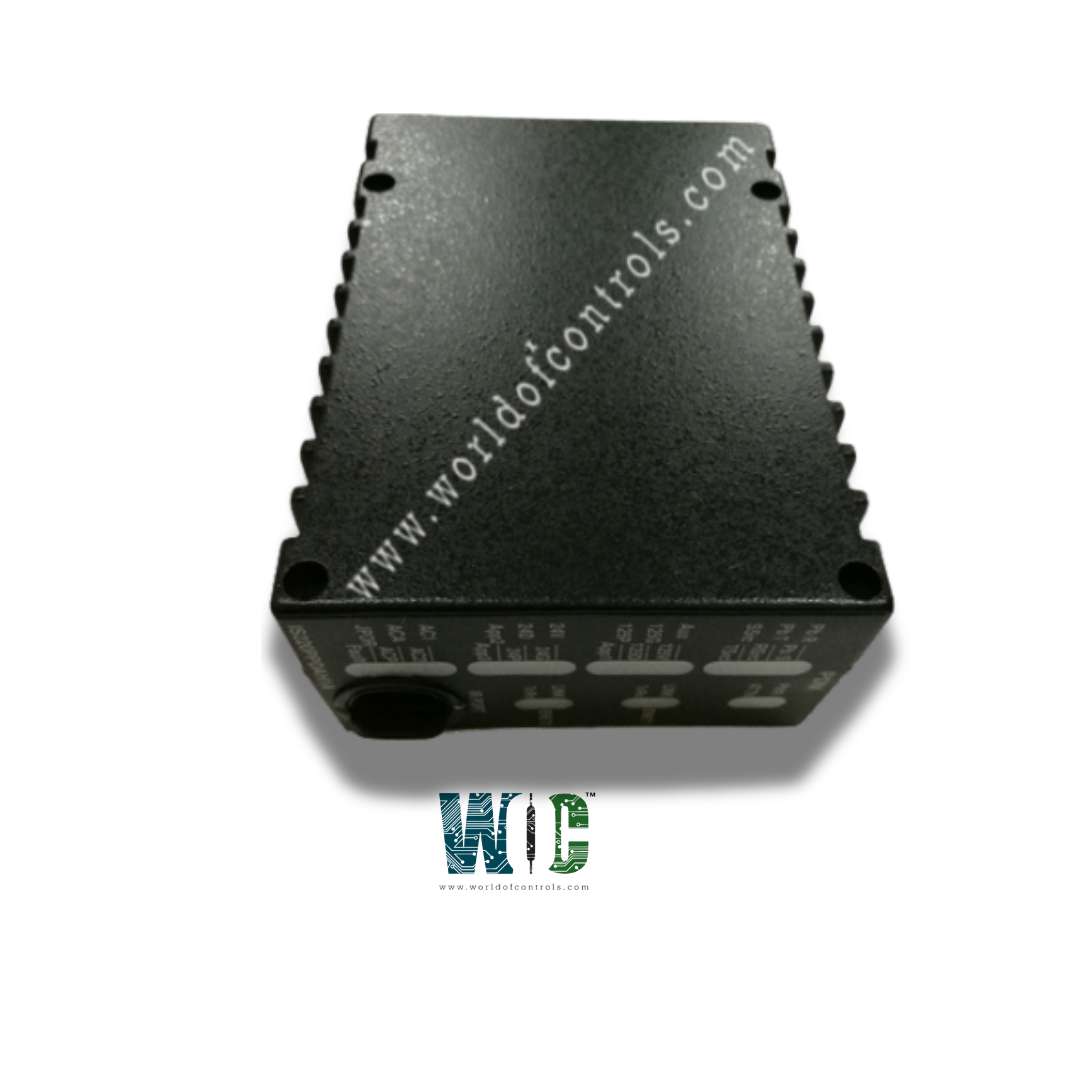
World Of Controls understands the criticality of your requirement and works towards reducing the lead time as much as possible.
IS220PPDAH1A, REV C - Power Distribution System Feedback I/O Module is available in stock which ships the same day.
IS220PPDAH1A, REV C - Power Distribution System Feedback I/O Module comes in UNUSED as well as REBUILT condition.
To avail our best deals for IS220PPDAH1A, REV C - Power Distribution System Feedback I/O Module, contact us and we will get back to you within 24 hours.
SPECIFICATIONS:
Part Number: IS220PPDAH1A, REV C
Manufacturer: General Electric
Series: Mark VIe
Product Type: Power Distribution System Feedback I/O Module
Power Supply: 24V DC
Input Voltage Range: 0-600V AC/DC
Current Measurement Range: 0-100A
Power Factor Range: 0.00 to 1.00
Frequency Measurement: 45-65 Hz
Digital Inputs: 4-32 channels
Communication Protocols: Modbus RTU/TCP
Connectivity: RS-485
Operating Temperature: -20°C to +70°C
Mounting Options: DIN Rail
Availability: In Stock
Country/Region of Manufacture: United States
Manual: GEH-6721D
FUNCTIONAL DESCRIPTION:
IS220PPDAH1A, REV C is a Power Distribution System Feedback I/O Module manufactured and designed by General Electric as part of the Mark VIe Series used in Distributed Control Systems. The PPDA I/O pack accepts inputs from up to six different power distribution boards. It conditions the board feedback signals and provides a dual redundant Ethernet interface to the controllers. PPDA feedback is structured to be plug and play uses electronic IDs to determine the power distribution boards wired into it. This information is then used to populate the IONet output providing correct feedback from connected boards. The PPDA I/O pack is hosted by the JPDS or JPDM 28 V dc Control Power boards on the Mark VIe Modular Power Distribution (PDM) system. It is compatible with the feedback signals created by JPDB, JPDE, and JPDF.
INSTALLATION:
SIGNAL ROUTING:
The JPDG, JPDS, JPDM, or JPDC board is where the PPDA I/O pack is mounted. 50-pin ribbon cable jumpers wired pin to pin 1 are used to connect other boards. One feedback group is contributed to PPDA by each board. There are up to five prior boards that this connection goes through. Feedback groups are shown in the above diagram as bold lines, and each board's connectors P1 and P2 are also shown. JPDM uses two sets of feedback signals because that board has a substantial number of feedback lines. Utilizing two boards is supported by JDPM. The following illustration represents the setup. The PPDA I/O pack and connectors on the JPDS board are as follows, going from right to left:
DIAGNOSTICS:
WOC holds the largest inventory of GE Distributed Control System Replacement Parts, offering both unused and rebuilt components, all backed by a warranty. Our expert team is available 24/7 to support your OEM needs and assist with any automation requirements. For pricing and availability of parts or repair services, contact us by phone or email.
How does the module function within a power distribution system?
The module connects to sensors and transformers to collect electrical data and transmits it to control systems via communication protocols like Modbus or Ethernet/IP. It enables automation by providing real-time insights, helping prevent failures, balance loads, and improve energy efficiency.
What parameters can the module monitor and control?
It monitors phase voltage, line voltage, current, power factor, active and reactive power, frequency, and harmonic distortion (THD). Some models also track environmental factors like temperature and humidity to prevent system overheating.
What communication protocols does the module support?
The module supports industry-standard communication protocols such as Modbus RTU/TCP, Profibus, Profinet, EtherNet/IP, CANbus, and IEC 61850. These protocols ensure seamless integration with PLCs, SCADA systems, and remote monitoring platforms.