World Of Controls understands the criticality of your requirement and works towards reducing the lead time as much as possible.
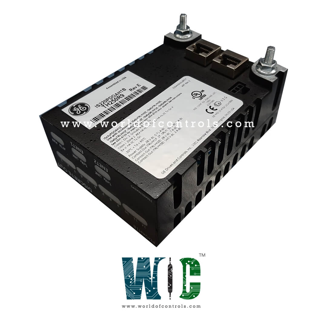
IS220PDOAH1B, REV C - Discrete Output Module is available in stock which ships the same day.
IS220PDOAH1B, REV C - Discrete Output Module comes in UNUSED as well as REBUILT condition.
To avail our best deals for IS220PDOAH1B, REV C - Discrete Output Module, contact us and we will get back to you within 24 hours.
Part No.: IS220PDOAH1B, REV C
Manufacturer: General Electric
Series: Mark VIe
Size: 8.26 cm high x 4.19 cm wide x 12.1 cm deep
Number of relay channels: 12 relays
Availability: In Stock
Country of Manufacture: United States (USA)
IS220PDOAH1B, REV C is a Turbine Discrete Output Module developed by GE. This module is part of the Discrete Output (PDOA) pack, which provides the essential electrical interface between one or two I/O Ethernet networks and a discrete output terminal board. The PDOA pack enables precise control and monitoring of discrete outputs, facilitating reliable communication between networked components and the output terminal.
Step 1: Mounting the Terminal Board
To begin the installation of the PDOA pack, first, securely mount the desired terminal board in the appropriate location within the system. Ensure that the terminal board is aligned correctly to prevent any misalignment issues during the connection process.
Step 2: Connect the PDOA Pack to the Terminal Board
Once the terminal board is securely mounted, directly plug the PDOA I/O pack into the terminal board connectors. This establishes the necessary electrical connections for signal transmission between the pack and the terminal board.
Step 3: Securing the PDOA Pack
After connecting the PDOA pack to the terminal board, mechanically secure the packs using the threaded studs located adjacent to the Ethernet ports. These studs are designed to slide into a mounting bracket that is specific to the terminal board type. It’s important to adjust the bracket location so that no right-angle force is applied to the DC-37 connector between the pack and the terminal board. This adjustment ensures the integrity of the connection. Once adjusted, the bracket will hold the pack in place, and this adjustment should only need to be performed once during the product’s lifetime.
Step 4: Connecting Ethernet Cables
Next, plug in one or two Ethernet cables, depending on the system configuration. The pack is designed to operate over either port, with dual connections available for redundancy. If dual connections are used, the standard practice is to connect ENET1 to the network associated with the R controller.
Step 5: Applying Power
To apply power to the PDOA pack, simply plug in the connector on the side of the pack. There is no need to remove power from the cable before plugging it in, as the PDOA pack is equipped with a soft-start capability that controls the current inrush when power is applied. This feature ensures that the pack powers up smoothly without causing damage to the components.
Step 6: Configuration Using ToolboxST
Once the PDOA pack is physically installed and powered, use the ToolboxST application to configure the I/O pack as necessary. The application provides the necessary interface for adjusting settings, monitoring performance, and troubleshooting. For additional information, refer to the Auto-Reconfiguration section in the relevant documentation for further guidance on setting up the system.
The PDOA pack mounts directly onto Mark VIe terminal boards. There are two types of terminal boards supported:
World of Controls has the most comprehensive collection of GE Mark VIe components. Please contact WOC as soon as possible if you require any extra information.
What is IS220PDOAH1B, REV C?
It is a Discrete Output Module developed by GE.
How does the self-test process work during startup?
At power-up, the module performs a self-test that checks the RAM, flash memory, Ethernet ports, and processor board hardware. This ensures that all components are functioning correctly before the module is deployed for operation.
What happens if there is a discrepancy in the relay feedback?
If the commanded state of a relay does not match the feedback from the output circuit, the module generates an alert. This helps operators quickly identify any discrepancies and take corrective actions to ensure reliable system performance.
Can the diagnostic signals be reset?
Yes, the diagnostic signals can be latched and later reset using the RESET_DIA signal once the system returns to a healthy state. This feature simplifies the troubleshooting process and helps in maintaining the system’s reliability.