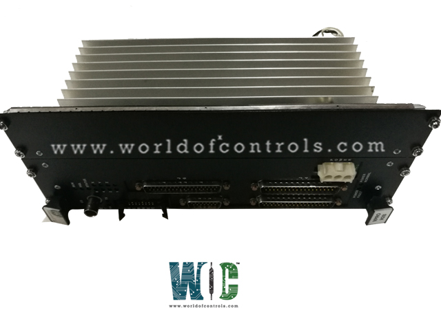
SPECIFICATIONS
Part No.: IS215VPWRH1AC
Manufacturer: General Electric
Series: Mark VI
Function: Protection Board
Size 17.8 cm Wide x 33.02 cm High (7.0 in x 13 in)
Availability: In Stock
Country of Manufacture: United States (USA)
Functional Description
IS215VPWRH1AC is a protection board developed by GE. It is a part of the Mark VI control system. Primary functions of the board is to facilitate the emergency trip function within the control system. This critical feature ensures rapid response to overspeed conditions, helping to prevent turbine damage or catastrophic failures. The board supplies speed signals enabling it to implement emergency overspeed (EOS) protection for the turbine. This capability is crucial for maintaining safe operating conditions and preventing the turbine from exceeding its designated speed limits.
Protection Board Features
- Generator Signals for Backup Synchronization Check Protection: In addition to overspeed protection, the board provides generator signals necessary for backup synchronization check protection. This functionality ensures proper synchronization between the turbine generator and the electrical grid, enhancing system stability and reliability.
- Analog Current Inputs: The board features three analog current inputs, which serve various monitoring and control purposes within the turbine system. These inputs enable real-time monitoring of critical parameters, facilitating proactive maintenance and troubleshooting activities.
- Thermocouple Inputs for Exhaust Over-temperature Protection: The board is equipped with nine thermocouple inputs, primarily dedicated to exhaust over-temperature protection on gas turbines. These inputs monitor exhaust temperatures, helping to prevent overheating and mitigate the risk of turbine damage or performance degradation.
- Integration with Mark VI Control System: As an integral part of the Mark VI control system, the board seamlessly interfaces with other system components, ensuring cohesive operation and comprehensive protection for turbine assets.
- Ensuring Safety and Reliability: By providing essential protection functions such as overspeed, synchronization check, and over-temperature protection, the board plays a crucial role in ensuring the safety, reliability, and longevity of turbine operations.
Installation Guidelines
- Identify Wiring Connections: Begin by identifying the wiring connections required for the various sensors and inputs that interface with the board. These connections typically include generator and bus potential transformers, analog inputs, thermocouples, and magnetic speed pickups.
- Terminal Block Wiring: The wiring connections are typically organized into terminal blocks on the TPRO module, which interfaces with the board. Generator and bus potential transformers, analog inputs, and thermocouples are wired to the first terminal block on the TPRO module. These connections provide essential input signals for monitoring turbine operations. Magnetic speed pickups, which detect rotational speed, are wired to the second terminal block on the TPRO module.
- Configuration Jumpers: The board features configuration jumpers, such as JP1A and JP1B, which determine the input type for the analog inputs. Set jumpers JP1A and JP1B according to the desired input type for the first of the three analog inputs. Depending on the application requirements, these jumpers can be configured to provide either a 4-20 mA current input or a voltage input.
- Ensure Proper Connection: Double-check all wiring connections to ensure they are properly secured and connected to the appropriate terminals on the TPRO module. Verify that jumpers JP1A and JP1B are correctly set according to the specified input type for the analog inputs.
- Power Up and Testing: Once the board is installed and wired correctly, power up the Mark VI control system and perform comprehensive testing to verify proper functionality. Test each input and sensor connected to the board to ensure accurate signal acquisition and processing.
- Final Checks and Calibration: Conduct final checks to confirm that all connections are secure and that the board is functioning as expected. If necessary, calibrate the analog inputs and perform any additional configuration steps to optimize system performance.
World of Controls has the most comprehensive collection of GE Mark VI components. Please contact WOC as soon as possible if you require any extra information.
Frequently Asked Questions
What is IS215VPWRH1AC?
It is a Protection Board designed and manufactured by GE.
What are the characteristics of the Magnetic Pickup (MPU)?
The MPU has an output resistance of 200 ohms and an inductance of 85 mH.
What is the output voltage generated by the MPU?
The MPU generates a voltage of 150 V peak-to-peak (p-p) into a load of 60 K ohms at the TPRO terminal block.
Is the output voltage of the MPU sufficient to cause a spark?
No, the output voltage of the MPU is insufficient to cause a spark, ensuring safety during operation.
What is the maximum short circuit current of the MPU?
The maximum short circuit current of the MPU is approximately 100 mA, providing protection against overload conditions.
