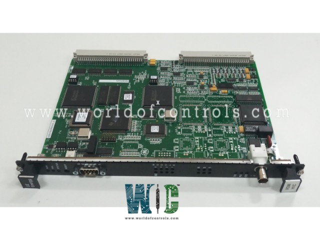
SPECIFICATIONS
Part No.: IS215VCMIH1CC
Manufacturer: General Electric
Country of Manufacture: United States of America (USA)
Size: 10.16 cm wide x 33.02 cm high
Temperature: -30 to 65oC
Type: 6U high VME board
Processor: TMS320C32
SRAM: 256k x 32
Flash memory: 4096K x 8-VCMIH_C
Technology: Surface-mount
Product Type: Communication Board
Availability: In Stock
Series: Mark VI
Functional Description
IS215VCMIH1CC is a communication board developed by GE. It is a part of Mark VI control system. VCMI board is a component within the control and interface module, facilitating internal communication between I/O boards in its rack and other VCMI boards via the IONet.
Features
- Communication Capabilities: Internally communicates with the I/O boards within its rack and other VCMI boards through the IONet, a dedicated communication network within the system architecture.
- Simplex Version: Equipped with one Ethernet IONet port, primarily designed for simplex systems where a single control module is connected to one or multiple interface modules via a single cable.
- TMR Version: Incorporates three Ethernet ports tailored for Triple Modular Redundancy (TMR) systems. It serves communication purposes with three I/O channels (Rx, Sx, and Tx) and interfaces with two additional control modules within the system setup.
- Configuration in TMR Systems: In TMR systems, the VCMI with three separate IONet ports establishes connections with individual I/O channels (Rx, Sx, Tx), facilitating redundant communication among these channels and other control modules.
- Fault Tolerance Mechanism - SIFT Voting: Implemented Fault Tolerance (SIFT) voting methodology. Input data received from each IONet connection undergoes voting processes within the R, S, and T VCMI boards. The voting results are transmitted to the control signal database (labeled UCVx in the diagram) housed within the controllers via the backplane VME (Versa Module Eurocard) bus for further processing and decision-making.
- Redundancy and Reliability: The redundancy and fault-tolerant architecture, particularly in TMR systems, ensure robust communication pathways and data reliability, enhancing the system's overall reliability and resilience against failures.
System Power Source
- Reliable power is essential for the proper functioning of the rack power supplies, which are supplied through various sources. One of the primary sources is a battery backup, which ensures a dependable power supply during outages or fluctuations. In addition to the battery backup, the system utilizes multiple power converters, which contribute to the primary power supply. By employing a combination of battery backup and multiple power converters, the system achieves enhanced redundancy, ensuring continuous power availability.
- The various power sources are interconnected in a configuration known as "high select" within the Power Distribution Module (PDM). This arrangement is critical for establishing redundancy, as it allows for seamless switching between power sources. The high select mechanism guarantees that the system maintains continuous and stable power delivery, even in the event of a power source failure.
- To create a floating direct current (DC) bus with a single ground connection, a balancing resistor network is employed. This network generates two outputs from the 125 V DC input: +62.5 V DC (designated as P125) and -62.5 V DC (designated as N125). These outputs are vital for supplying power to the system racks and terminal boards, ensuring that all components receive the necessary voltage for optimal performance.
- The Power Distribution Module (PDM) is equipped with ground fault detection mechanisms, which play a crucial role in maintaining system integrity. The design of the system allows it to tolerate a single ground fault without compromising performance or causing fuses to blow. Although the fault is identified promptly for quick rectification, the system continues to function normally, ensuring that there is no loss of performance. Once the fault has been identified, repairs can be made without affecting the overall operation of the system.
Product Attributes
- It utilizes IONet as the primary medium for transmitting data between modules within the system. IONet represents a specialized form of Ethernet specifically tailored for Mark control I/O packs and controllers. Notably, it operates using the IEEE 1588 protocol, ensuring precise synchronization and coordination of data transmission.
- When a card is integrated into the Control Module, it assumes the role of the IONet bus master. In this capacity, it orchestrates communication with slave stations via Ethernet 10Base2 network connections. Typically, a VCMI card is installed in the three control modules within a triple-redundant setup, reinforcing system reliability and resilience.
- Data exchange among these cards is facilitated and subjected to a voting process to ensure data integrity and accuracy. Only after the data has been mutually verified is it forwarded to the main processor card to execute applications, thereby maintaining the system's robustness and fidelity to operational requirements. The implementation of IONet and technology, it enables efficient and dependable communication among system components, crucial for the seamless operation of industrial processes.
The WOC team is always available to help you with your Mark VI requirements. For more information, please contact WOC.
Frequently Asked Questions
What is IS215VCMIH1CC?
It is a communication board developed by GE under the Mark VI series.
Which power supply buses are monitored internally?
The 5 V, 12 V, 15 V, and 28 V power supply buses are internally monitored.
What diagnostic signals are monitored from the Power Distribution Module (PDM) through J301?
Diagnostic signals from the PDM through J301 include ground fault, over/under voltage on the P125 V bus, two differential 5V dc analog inputs (P28A and PCOM), and digital inputs.
