World Of Controls understands the criticality of your requirement and works towards reducing the lead time as much as possible.
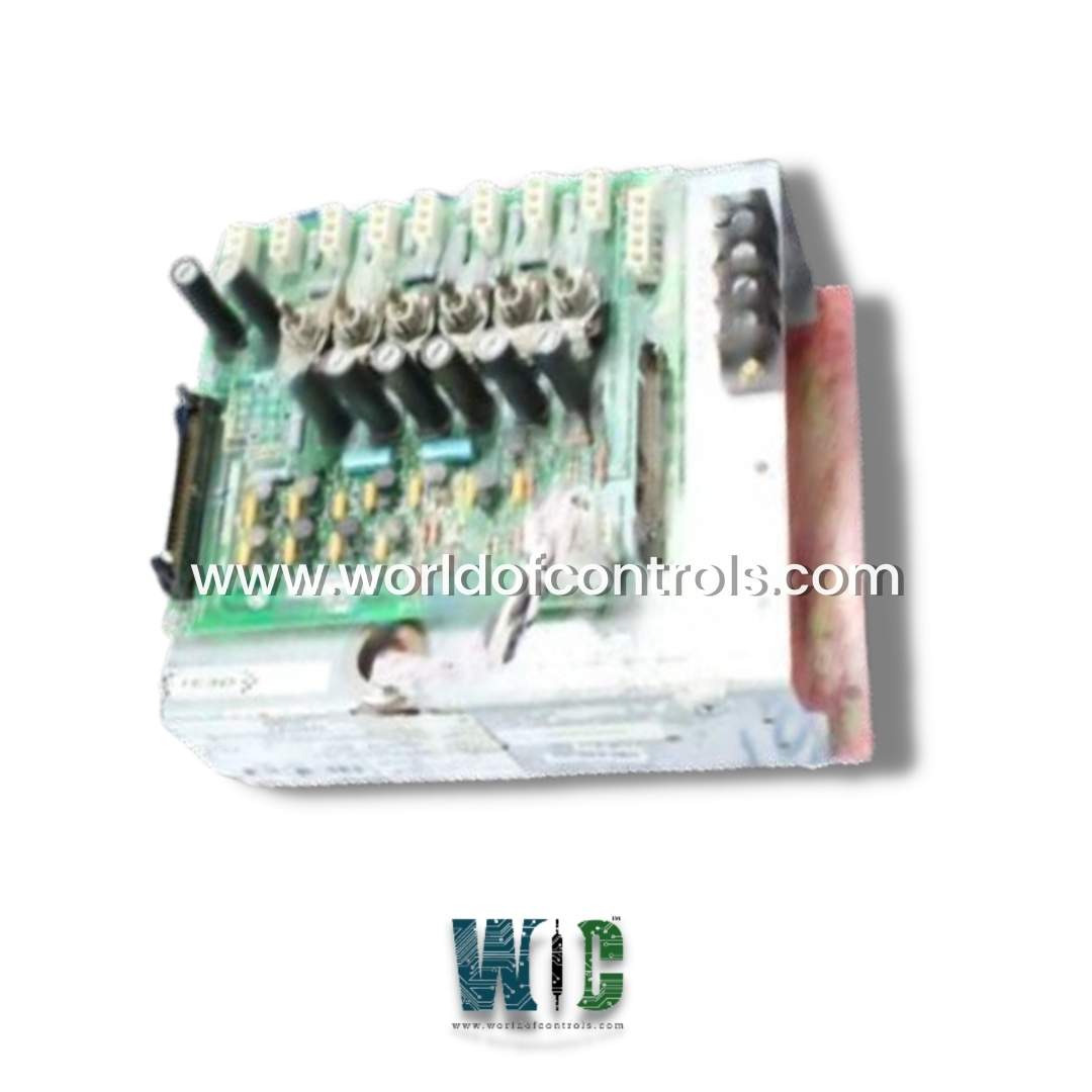
IS2020JPDCG02 - Power Junction Distribution Module is available in stock which ships the same day.
IS2020JPDCG02 - Power Junction Distribution Module comes in UNUSED as well as REBUILT condition.
To avail our best deals for IS2020JPDCG02 - Power Junction Distribution Module, contact us and we will get back to you within 24 hours.
SPECIFICATIONS:
Part Number: IS2020JPDCG02
Manufacturer: General Electric
Series: Mark VIe
Board rating: 125 V dc
Product Type: Power Junction Distribution Module
Impedance to the ground: 75 Ohm
Power Requirements: +5 V dc, 6 A
Operating temperature: -30 to +65°C
Size: 30.48cm High x 21.33cm
Mounting: 4 mounting Holes
Repair: 3-7 Day
Availability: In Stock
Country of Origin: United States
Manual: GEH-6721G
FUNCTIONAL DESCRIPTION:
IS2020JPDCG02 is a Power Junction Distribution Module manufactured and designed by General Electric as part of the Mark VIe Series used in GE Distributed Control Systems. The Power Junction Distribution Module is essential for managing and distributing multiple power supplies throughout the system. It efficiently directs 125 V DC, 115/230 V AC, and 28 V DC to various boards and components, ensuring that each part of the control system receives the required power. Designed to endure the challenging conditions of industrial settings, this module is a reliable choice for maintaining stable and efficient turbine operations.
INSTALLATION:
The JPDC module is generally installed in a vertical orientation, with the 115/230 V AC input connector (JAC) positioned at the bottom. It is secured using four screws, which fit into mounting holes located at the top and bottom of the module’s base. While placement within the control cabinet is flexible, distribution boards are typically mounted toward the lower part of the cabinet to support grounding, as outlined in the Grounding section. The optional PPDA I/O pack connects to the JA1 connector and is fastened to the JPDC base via an angle bracket, held securely in place by nuts threaded onto pre-attached studs. Diagnostic input signals from other distribution boards are routed to the JPDC through a 50-pin ribbon cable connected to P2.
OPERATION:
The JPDC receives an input of either 115 V AC or 230 V AC through connector JAC, with a maximum allowable current of 12.5 amps RMS. It is recommended that the low or neutral side of the input power be grounded (refer to the functional diagram). The module provides two AC outputs, both safeguarded by a 10 A time-delay fuse on the high side only (Pin 1 of each connector). The output at JAC1 is controlled by toggle switch SWAC1, while the output at JAC2 remains unswitched.
The JPDC module can accept two battery inputs via connectors JD1 and JD2, as well as a third 125 V DC input from an AC/DC converter, such as the IS2020DACA, through connector JZ2. Each input typically passes through an external filter, with an input voltage range of 90 to 145 V DC. The two battery inputs are combined using diode module D1, and they are further merged with the 125 V DC from the DACA module via a diode on the DACA module. These combined 125 V DC inputs create a 125 V DC bus on the JPDC, labeled PDC, with return paths connected and labeled NDC. The total 125 V DC should not exceed 20 amps. All three 125 V DC inputs are isolated from the ground. Installing jumper JP2 connects each side of the 125 V DC bus to FE ground through approximately 84 k ohms of resistance, enabling ground fault detection.
WOC has the largest stock of OEM replacement parts for GE Distributed Control Systems. We can also repair your faulty boards and supply unused and rebuilt boards backed up with a warranty. Our team of experts is available round the clock to support your OEM needs. Our team of experts at WOC is happy to assist you with any of your automation requirements. For pricing and availability on parts and repairs, kindly contact our team by phone or email.
What is the main function of the Power Junction Distribution Module?
This module manages and distributes various power supplies within a control system, ensuring that components receive stable power under demanding industrial conditions.
What types of power inputs can the module handle?
The module accepts 125 V DC, 115/230 V AC, and 28 V DC power inputs, which it distributes to various components in the control system.
What is the maximum current capacity for AC input?
For AC input at 115 or 230 V through connector JAC, the maximum allowable current is 12.5 amps RMS.
Are AC outputs protected in the module?
Yes, both AC outputs are protected by a 10 A time-delay fuse on the high side, with JAC1 being controlled by toggle switch SWAC1, while JAC2 remains unswitched.