SPECIFICATIONS
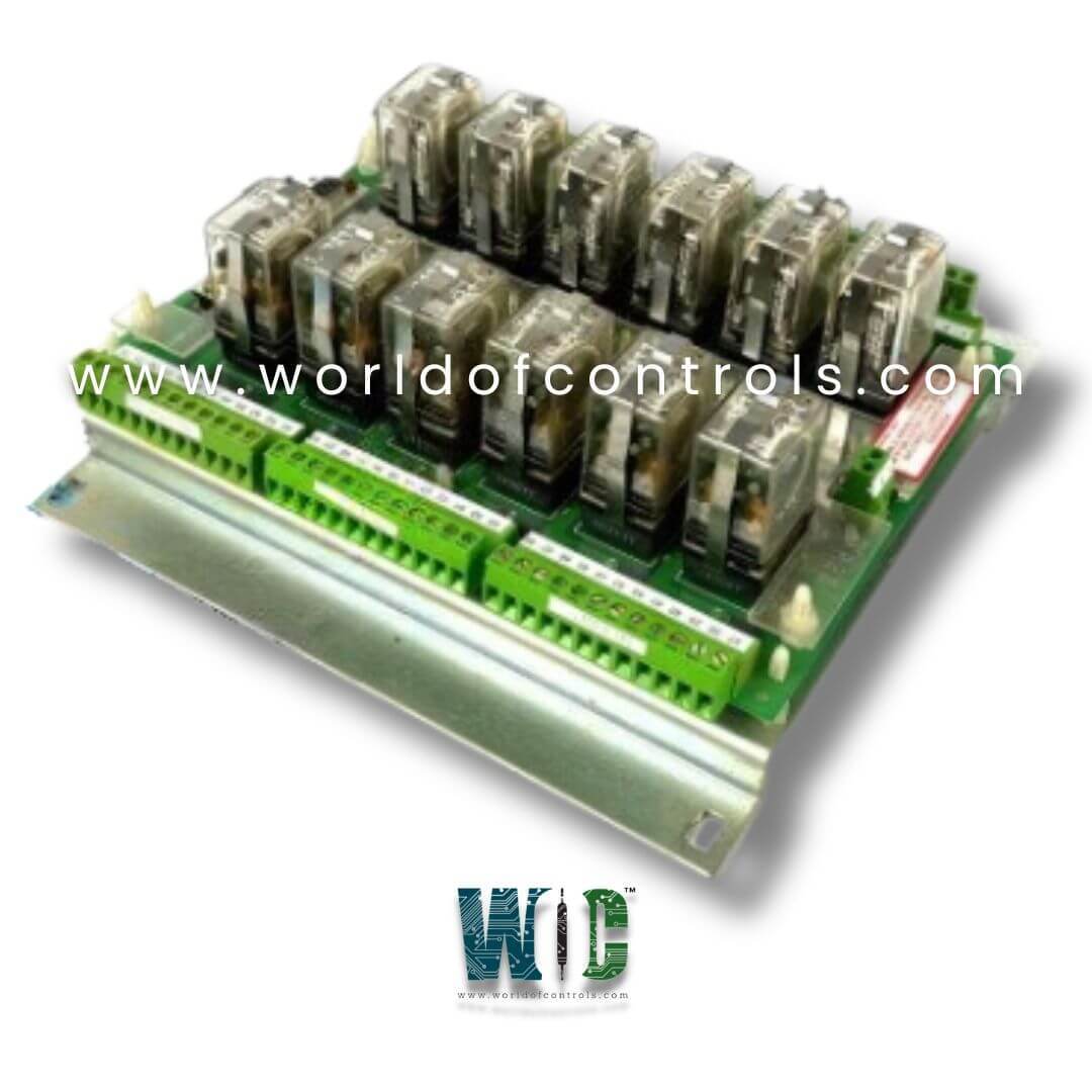
Part No.: IS2020DRLYH1B
Manufacturer: General Electric
Country of Manufacture: United States of America (USA)
Technology: Surface mount
Temperature: -30 to 65oC
Product Type: Relay Output Terminal Board
Availability: In Stock
Series: Mark VI
Functional Description
IS2020DRLYH1B is a Relay Output Terminal Board developed by GE. It is a part of the Mark VI control system. Simplex Relay Output (DRLY) terminal board represents a versatile solution for relay output applications, characterized by its compact design and efficient functionality. Unlike terminal boards designed for DIN-rail mounting, the DRLY board is specifically engineered for wall mounting, offering flexibility in installation configurations.
Key Features
- At the core of the terminal board are 12 form-C dry contact output relays, providing reliable switching capabilities essential for a wide range of control and automation tasks. This versatile configuration caters to diverse industrial applications, allowing for seamless integration into various control systems.
- The terminal board is designed to interface effortlessly with the VCCC, VCRC, or VTUR processor board via a single cable connection. This streamlined connectivity simplifies installation procedures and enhances system efficiency by minimizing potential points of failure.
- The 37-pin cable connector utilized by the board is identical to those found on the larger board, ensuring compatibility and ease of interchangeability within the system.
- During installation, the terminal board offers a straightforward setup process. Its wall-mounting design allows for secure attachment through the four mounting holes strategically positioned on the metal support plate. This ensures stability and reliability in operation, even in demanding industrial environments.
- To establish relay output connections, wires for the 12 relay outputs are directly connected to the odd-numbered screws on the terminal blocks.
- This organized wiring configuration simplifies installation and maintenance tasks, enabling efficient signal routing and troubleshooting procedures.
Installation Procedure
- Pre-Installation Considerations: Before proceeding with the installation of the terminal board, it's essential to note that it does not feature a shield terminal strip. This distinction is important for ensuring proper installation and functionality within the control system.
- Mounting: To begin the installation process, securely mount the board onto the desired wall surface. This is accomplished by fastening screws through the four mounting holes located in the corners of the metal support plate. Ensuring a tight and secure attachment is crucial for maintaining stability and reliability during operation.
- Connecting Relay Outputs: Once the board is securely mounted, proceed to connect the wires for the 12 relay outputs. Direct these wires to the odd-numbered screws on the terminal blocks, ensuring a direct and secure connection. This organized approach simplifies wiring configuration and facilitates efficient signal transmission within the control system.
- Utilizing Euro-Block Terminal Blocks: The terminal board is equipped with high-density Euro-Block type terminal blocks, designed to streamline connectivity and ensure optimal signal transmission. These terminal blocks plug into the numbered receptacles on the board, providing a convenient interface for connecting relay output wires.
- Establishing SCOM Connection: TB2 features two screws designated for the SCOM (chassis ground) connection. It's imperative to establish this connection with utmost care, ensuring that the distance between the SCOM connection and the chassis is kept as short as possible. This minimizes the risk of ground loops and enhances system performance and safety.
- Finalizing Installation: Once all connections have been made, double-check the integrity of the wiring and ensure that the DRLY board is securely mounted to the wall. Perform a thorough inspection to verify that all connections are tight and secure, minimizing the risk of wiring errors or loose connections during operation.
Operation
- The operation of the relay module is tailored for precise control in industrial settings, offering essential functionality without solenoid source power integration. Each relay within the module is equipped with one set of dry contacts, featuring two normally open (NO) contacts in series. Unlike the TRLY module, DRLY does not incorporate on-board suppression mechanisms or relay state monitoring capabilities.
- For operation, the relay coils in the module are powered by 28 V DC provided by the I/O board (such as VCCC, VCRC, or VTUR). This power supply is visually indicated by a green LED on the module, ensuring clear status identification of active coil power.
- Each relay in the DRLY module is equipped with a yellow LED that indicates the presence of voltage across the relay coil. This LED provides visual feedback, confirming the operational status of each relay and aiding in diagnostic checks.
- In scenarios where the control cable is unconnected or inactive, the relays default to a de-energized state. This default state ensures safety and prevents unintended activation of connected devices or systems in the absence of control signals.
The WOC team is always available to help you with your Mark VI requirements. For more information, please contact WOC.
Frequently Asked Questions
What is IS2020DRLYH1B?
It is a relay output terminal board developed by GE under the Mark VI series.
What is the purpose of the ID device on the terminal board connector?
The ID device serves to provide crucial information about the terminal board to the I/O board. This information includes the board's serial number, type, and revision number, encoded into a read-only chip. When the chip is read by the VCCC/VCRC or VTUR, any mismatch encountered triggers a hardware incompatibility fault, ensuring compatibility and system integrity.
How are relay coil voltages indicated on the terminal board?
The voltage across each relay coil is conveniently indicated by a yellow LED. This visual indicator provides real-time feedback on the status of the relay coil voltage, allowing for quick and easy monitoring during operation or troubleshooting.
How is the 28 V supply to the board indicated on the terminal board?
The presence of the 28 V supply to the board is visually indicated by a green LED. This LED serves as a convenient indicator, confirming the availability of power to the board. By monitoring the status of the green LED, operators can ensure that the board is properly powered and ready for operation.
