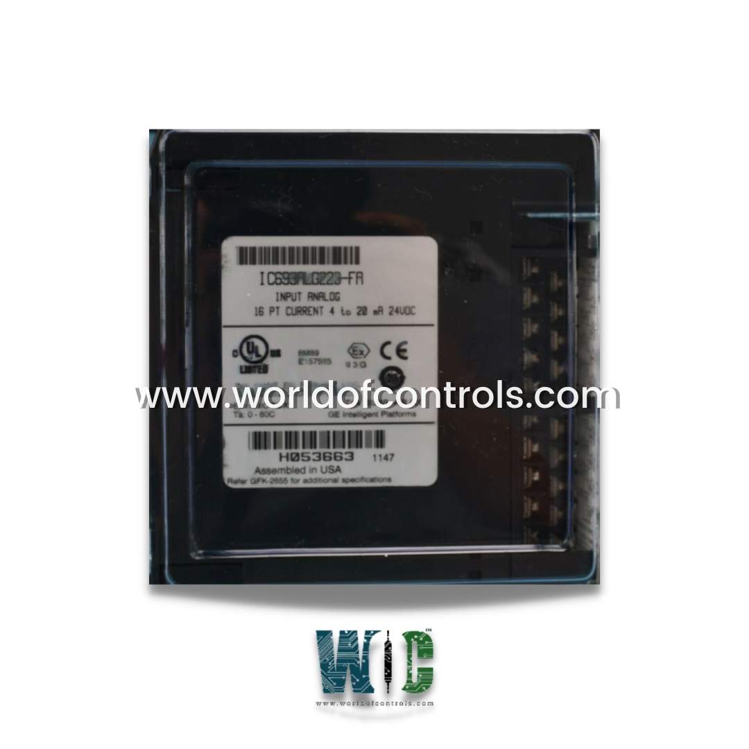
SPECIFICATIONS
Part No.: IC693ALG223
Manufacturer: General Electric
Country of Manufacture: United States of America (USA)
No. of channels: 1 to 16 selectable
Input Current Range: 0 to 20 mA, 4 to 20 mA and 4 to 20 mA enhanced
Update Rate: 13 msec
Power Consumption: 120 mA or 65 mA
Product Type: RX3i Analog Current Input Module
Availability: In Stock
Series: Mark I and II
Functional Description
IC693ALG223 is an RX3i Analog Current Input Module developed by GE. It is part of the Fanuc system. It is a highly versatile Analog Current Input Module designed for use with the PACSystems Series 90-30 and RX3i control systems. It features 16 channels and offers a range of configuration options to suit various application needs.
Features
- Channel Configuration: The module provides 16 separate, single-ended analog current input channels. These channels can be configured for three different input ranges:
- 4 to 20 mA
- 0 to 20 mA
- 4 to 20 mA Enhanced
- The enhanced range allows for additional functionality, including open wire fault detection and high and low alarm settings.
- Alarm Functionality: Each input range supports both high and low alarm settings. For the enhanced range, users can set a low alarm limit to detect open wire faults, and high alarm alerts can also be configured based on application requirements.
- Reporting and Status: The module reports various status indicators to the CPU, including power supply status, ensuring reliable operation and easy monitoring.
- Power Consumption: The module consumes 120 mA from a 5 VDC bus on the controller backplane. Additionally, it requires 65 mA plus current loop from a user-supplied +24 VDC supply.
- Performance and Isolation: The module features a standard update rate of 6 milliseconds. It offers robust isolation with a continuous rating of 250 VAC and a one-minute rating of 1500 VAC, ensuring reliable operation in various industrial environments.
- Scanning and Calibration: During operation, the module scans active channels in serial order. The analog values are scaled across the entire range of the converter, with factory calibration ensuring accurate value adjustment per bit.
- Compatibility and Firmware: The module is compatible with RX3i racks and supports firmware upgrades. However, firmware upgrades are not supported for 90-30 racks.
- LED Status Indicators: The module is equipped with LED status lights that indicate ON, OFF, and FAIL conditions. These indicators assist users with operational monitoring and troubleshooting.
Current Ranges
- The default range is set at 4 to 20 mA, where 4 mA corresponds to a count of 0, and 20 mA corresponds to a count of 32,000. This range is commonly used in standard industrial applications that utilize current loops for signal transmission.
- The module allows for a configurable range of 0 to 20 mA. In this configuration, 0 mA corresponds to a count of 0, and 20 mA corresponds to a count of 32,000. Users can modify this setting through the IC641 configurator software or a Hand-Held Programmer, and the full 12-bit resolution is maintained throughout this range for accurate signal processing.
- The module also features an Enhanced Range of 4 to 20 mA. In this setup, 0 mA corresponds to a count of -8,000, 4 mA to a count of 0, and 20 mA to a count of 32,000. This configuration provides automatic scaling for the 4 to 20 mA range while also offering negative values for currents between 0 and 4 mA. This feature is particularly beneficial for detecting open-wire faults, as it includes a low alarm limit that activates when input currents drop below 4 mA, alerting users to potential issues such as broken connections or faulty wiring.
Power Requirements and LEDs
- The power requirements for the module are essential for ensuring its proper functionality within the system. It consumes 120 mA from the 5V bus on the PLC backplane, which provides the necessary power for basic operations. Additionally, the module requires 65 mA from a user-supplied +24V supply, along with any current loop currents that are connected (as detailed in Table 3-13 of the specifications). This dual power supply setup is crucial for the module to function efficiently and accurately in a variety of applications.
- In terms of LED indicators, the module is equipped with two green LEDs that serve to provide status information for both the module and the user supply. The top LED, labeled MODULE OK, provides critical status information during power-up. It functions as follows:
- When the LED is ON, it indicates that the module status is OK and has been configured correctly.
- If the LED is OFF, it signals that there is either no backplane power or that the software is not running, which may occur if the watchdog timer has timed out.
- A continuous rapid flashing indicates that configuration data has not been received from the CPU, suggesting a communication issue.
- The LED may display slow flashes followed by OFF, which denotes failed power-up diagnostics or an encountered code execution error, indicating a malfunction or misconfiguration.
- The bottom LED, titled User Supply OK, serves a different purpose. It indicates that the user-provided 24V supply is within the specified range. When this LED is lit, it confirms that the analog side of the module is functioning properly, allowing for reliable operation and accurate data processing. Together, these LEDs offer valuable insight into the module's operational status and assist users in diagnosing any issues that may arise during use.
Configuration
It is a 16-Channel Analog Current Input module designed for the Series 90-30 Programmable Logic Controller (PLC). It is capable of converting up to 16 analog input channels into digital data for use by the PLC. The configuration of this module can be done using various tools, such as the Logicmaster 90-30/20/Micro Programming Software, the CIMPLICITY Control Programming Software, or a Hand-Held Programmer. These configuration tools enable users to customize various operational parameters to suit specific application needs.
Configuration Parameters
The module offers a range of configurable parameters that allow users to tailor the module's behavior to their requirements. The parameters are described in the table below, which includes default values, possible ranges, and the units for each setting. The configuration procedure for each tool is discussed in the following sections, enabling users to set up the module efficiently.
Key Configuration Parameters
- Active Channels: This parameter specifies how many of the 16 available input channels are active and used for data conversion. You can configure between 1 and 16 channels, depending on the needs of your application. The default value for configuration with the Logicmaster 90-30/20/Micro software is 1 channel, while the Hand-Held Programmer sets it to 16 active channels by default.
- Ref Adr (Reference Address): This is the starting address for the %AI reference type, which determines the memory location in the PLC where the analog input data will be stored. The standard range for this address is %AI0001 or the next highest available address. Proper configuration ensures that the converted analog values are correctly mapped to memory locations for easy access by the PLC.
- %I Size: This parameter defines the number of %I status locations to be allocated for the module's input channels. These locations store the status information about the analog signals. The available options are 8, 16, 24, 32, or 40 bits, allowing users to define how much status data is to be handled. The default value when using Logicmaster 90-30/20/Micro software is 8 bits, while the Hand-Held Programmer defaults to 40 bits.
- Range Type: The Range Type setting determines the input range for the analog current signal. The module supports multiple range options, including 4-20 mA (the default), 0-20 mA, and the enhanced 4-20+ range. The choice of range depends on the type of sensor or device providing the input signal. The default is set to 4-20 mA, which is the most commonly used range in industrial applications.
- Alarm Low: This parameter specifies the low alarm threshold for the analog input signals. If the signal falls below this threshold, an alarm will be triggered. The range for setting the alarm low value is from -8000 to +32759, with the default setting being 0 user counts. This allows users to set custom thresholds for alarm triggering based on the specific requirements of their application.
- Alarm High: Similar to the low alarm, the Alarm High parameter sets the upper threshold for triggering an alarm if the signal exceeds this value. The range for the high alarm value is from -7999 to +32760, with the default set at +32000 user counts. Users can modify this value according to the range of their analog input signals and the alarm conditions required for their system.
Configuration Tools
- Logicmaster 90-30/20/Micro Programming Software: Logicmaster 90-30/20/Micro is a software tool used to configure the module for Series 90-30 PLCs. The software allows users to define the number of active channels, select the reference address, set the alarm thresholds, and configure the range type. This tool is suitable for users who prefer configuring the module via a PC-based interface.
- CIMPLICITY Control Programming Software: CIMPLICITY is another software tool that provides advanced configuration and control capabilities for GE PLC systems. It supports the configuration of the module, including the parameters described above.
- Hand-Held Programmer: The Hand-Held Programmer is a portable configuration device that allows users to configure the module directly from the field. This tool is particularly useful when a PC-based setup is not available or practical. The programmer allows the user to set the active channels, reference address, and alarm limits, making it an easy-to-use option for on-site adjustments.
The WOC team is always available to help you with your Mark I and II requirements. For more information, please contact WOC.
Frequently Asked Questions
What is IC693ALG223?
It is an RX3i Analog Current Input Module developed by GE under the Mark I and II series.
What are the alarm capabilities of the module?
The module supports both high and low alarm settings for each range. In the enhanced range (4 to 20 mA), it includes open wire fault detection and allows the user to set high alarm alerts.
How does the module report status?
The module reports various statuses, including power supply status, to the CPU, helping to ensure reliable operation and facilitate monitoring.
What are the power requirements?
The module requires 120 mA from a 5 VDC bus on the controller backplane. 65 mA plus current loop from a user-supplied +24 VDC supply.