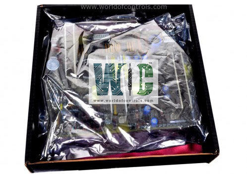
SPECIFICATIONS
Part No.: IC3600TFCV1
Manufacturer: General Electric
Series: Mark I and II
Product type: Firing Circuit
Operating temperature: -25°C to +55oC
Storage temperature -25°C to +85oC
Repair: 3-5 Days
Availability: In Stock
Country of Manufacture: United States (USA)
Functional Description
IC3600TFCV1 is a Firing Circuit developed by GE. It is a part of the Mark I and II control systems. Mark I and II Systems manage the turbine's operational performance, ensuring that it operates efficiently and effectively according to its intended application. This system primarily governs performance of the turbine.
Speed/Load Control Features
- The Speed/Load Control System is a critical component of gas turbines, managing the speed of the turbine output shaft to ensure optimal performance and stability. This system can operate in different modes depending on the application requirements, primarily focusing on speed control and load management.
- In isochronous control mode, the system maintains the turbine speed precisely at the setpoint, regardless of variations in load. This means that the turbine’s speed remains constant even if the load changes. Isochronous control is typically used in mechanical drive applications where maintaining a consistent speed is crucial, and the turbine is not synchronized with a larger system.
- Droop control allows the turbine speed to decrease as the load increases, providing a proportional response between speed and load. This mode is used in generator drive applications where the turbine operates in synchronization with a larger power system. In this scenario, the turbine's speed control function helps manage the load by adjusting according to the system’s demands. The system is always active except when the turbine reaches its maximum allowable exhaust temperature.
- For generator drive systems, the speed control function is continuously active. The setpoint determines the turbine’s load, and changes in the setpoint influence the turbine’s loading and unloading rates. Control inputs can come from local switches on the turbine or generator panel, or from remote raise/lower switches. Additionally, a load limiter can be employed to manage the maximum load based on signals proportional to the generator load. This load limiter allows for three load settings: spinning reserve, an intermediate preselected load, and maximum load.
- In mechanical drive applications, the turbine’s output is directly linked to the speed of the driven equipment. Here, the turbine speed is not synchronized with any external system, making isochronous control the preferred method to ensure consistent speed regulation.
- Setpoint Controller adjusts the turbine speed or load based on input commands. The set point can be modified using either local switches on the turbine or generator panel or remote raise/lower switches.
- Load Limiter regulates the maximum allowable load based on predefined settings and signals related to the generator load. It provides flexibility in managing load limits and ensures that the turbine operates within safe and efficient parameters.
- Operational dynamically adjusts the turbine speed according to the chosen control mode (isochronous or droop) and input commands. This ensures that the turbine operates efficiently and responds effectively to changes in load.
World of Controls has the most comprehensive collection of GE Mark IV components. Please contact WOC as soon as possible if you require any extra information.
Frequently Asked Questions
What is IC3600TFCV1?
It is a Firing Circuit developed by GE
How does the Speed/Load Control System operate in generator drive applications?
In generator drive applications, the system continuously manages turbine speed and load. The setpoint determines the turbine load, and adjustments to the setpoint influence the turbine’s loading and unloading rates. A load limiter may also be used to regulate maximum load based on generator load signals.
What role does the load limiter play in the system?
The load limiter regulates the maximum allowable load by providing predefined load settings, such as spinning reserve, an intermediate preselected load, and maximum load. It ensures that the turbine operates within safe and efficient load parameters.
How are setpoint adjustments made in the system?
Setpoint adjustments can be made using local switches on the turbine or generator panel or through remote raise/lower switches. These adjustments allow operators to control turbine speed and load as needed.
