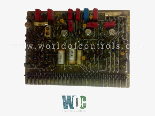
SPECIFICATIONS
Part No.: IC3600SPOA1D
Manufacturer: General Electric
Country of Manufacture: United States of America (USA)
Product Type: Peaking Operation Board
Availability: In Stock
Series: VersaMax
Functional Description
IC3600SPOA1D is a Peaking Operation Board. It is developed as part of the temperature control system for turbine operations. This board, commonly referred to as a Generator Drive Option, is equipped to generate peak and peak reserve biases for regulating turbine temperature. It contains specialized circuitry to manage temperature regulation effectively, making it an essential component in applications where temperature stability and control are critical, particularly during peaking operations and warm-up phases.
Key Functions
- Peak and Peak Reserve Bias Generation: This board generates both peak and peak reserve biases required by the temperature regulator. When both biases are needed, the outputs (PK and PR) are connected to provide the desired control over turbine temperature.
- Controlled Rate Increase: For both the PK and PR inputs, a "0" signal results in an increase of bias output at a controlled rate, governed by set limits on the board (R114 for PK and R118 for PR). This control enables gradual and safe adjustments to temperature.
- Sequential Logic: The card uses sequential logic, which adds PK and PR outputs for optimized peaking operations, allowing the system to handle peak reserve conditions smoothly.
Temperature Adjustments and Suppression
- PK Adjustments (R114): Provides an adjustment range from 0 to 150ºF above the base temperature, allowing flexibility in peaking conditions.
- ER Adjustments (R110): Allows for adjustments from 0 to 100ºF above peak temperature, offering further precision in temperature control.
- Warm-Up Suppression: During the warm-up phase, temperature suppression is enabled, where the temperature control bias follows the warm-up curve. The SHP3 card provides this follower circuit, ensuring that a safe temperature profile is maintained until the warm-up is complete.
Start-Up Suppression Mechanism
- Exhaust Temperature Bias: The exhaust temperature signal, derived from the STKK card, is integrated into the suppression bias to adjust the turbine’s temperature control based on the current exhaust temperature.
- Suppression Removal Rate: Once the warm-up phase is complete, the start-up suppression is removed at a default rate of 5ºF per second, with the option for different removal rates through jumper adjustments.
- Maximum Bias Option: The SFPB card provides an optional maximum warm-up bias, setting a limit for TX (temperature) during warm-up and preventing excessive temperature rise during initial operation.
Temperature Control System
- Thermocouple Temperature Feedback: Temperature feedback originates from up to 12 chromel-alumel thermocouples placed strategically within the turbine exhaust duct. These thermocouples provide real-time data on the exhaust temperature, which is crucial for precise temperature regulation.
- Signal Processing: Thermocouple signals are averaged, cold-junction compensated, and summed with reference signals to modulate the turbine's exhaust control. The reference signals may include base reference, start-up suppression, ambient bias, transient overfire, peak load, and peak reserve load.
- Temperature Control Loop: The temperature control loop consists of several cards, including STKK, SPOA, SHPB, SFPB, and a temperature averaging module. Together, these components ensure the turbine operates within safe temperature limits, adjusting for factors like transient temperature changes and overfire conditions.
Auxiliary Monitoring and Protection with ITS
- In certain control equipment, temperature regulation and protection are enhanced by the Integrated Temperature System (ITS). The ITS not only provides temperature control but also includes auxiliary monitoring and protection functions, expanding the system’s capability to handle various operational conditions.
- If ITS is implemented, the card’s temperature control features may be supplemented or replaced by ITS functionalities, which are outlined in the ITS instruction manual for comprehensive guidance on system operations.
The WOC team is always available to help you with your Mark I and II requirements. For more information, please contact WOC.
Frequently Asked Questions
What is IC3600SPOA1D?
It is a Peaking Operation Board developed by GE under the Mark I and II series.
What functions does the board perform?
The board primarily generates peak and peak reserve biases for temperature control. It also manages controlled rate increases for bias outputs, uses sequential logic for optimized peaking, and provides adjustable temperature suppression during turbine warm-up.
How are PK and PR biases used on this board?
The PK (Peak) and PR (Peak Reserve) outputs can be tied together to provide combined temperature control. 0 signal on either PK or PR initiates an increase in the output bias at a controlled rate until it reaches a set limit. This combined setup helps in managing temperature effectively during peak conditions.
How does the start-up suppression mechanism work on this board?
During turbine warm-up, a start-up suppression bias controls temperature to follow a safe warm-up curve. This suppression is removed at a rate of 5oF per second once warm-up is complete (other rates can be set via jumpers). An exhaust temperature signal, derived from the STKK card, adjusts the suppression bias based on the turbine’s current exhaust temperature.
