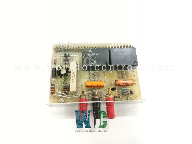
SPECIFICATIONS
Part No.: IC3600SCZA1B
Manufacturer: General Electric
Country of Manufacture: United States of America (USA)
Product Type: Single Source Circuit Board
Availability: In Stock
Series: Mark I and II
Functional Description
IC3600SCZA1B is a Single Source Circuit Board developed by GE. The module is part of Mark I and II series. It provides two variable frequency sources with a peak-to-peak voltage of 10 to 11 volts and a frequency range adjustable from 15 Hz to 12.5 kHz, producing a sine wave output. These signals are used to simulate speed signals from a pulse tach magnetic pick-up, aiding in calibrating the pulse rate to the analog circuit and speed control loop.
Variable Frequency Sources
- Voltage: Two sources provide 10 to 11 volts peak-to-peak.
- Frequency Range: These sources are variable from 15 Hz to 12.5 kHz (frequency period ranging from 66.7 milliseconds to 80.0 microseconds).
- Waveform: The output is a sine wave.
- Purpose: These variable frequency sources simulate a speed signal from a pulse tach magnetic pick-up. The simulation is useful for calibrating pulse rate to the analog circuit and the speed control loop.
Patchboard Output
The output of the two frequency sources is accessible on a patchboard:
- FREQ #1 is available at C1 (concerning ACOM).
- FREQ #2 is available at C10 (concerning ACOM).
- ACOM refers to the analog common ground, providing the reference point for these signals.
Power Supply
- The circuit is powered by the converter, which steps down from -50V to -12V, unless a dedicated -12V supply is available from the control system. If this supply is available, the -50V supply is not required.
- The circuit also requires a +12V supply from the control system to function properly.
- This configuration, often used in turbine control systems, ensures that the speed control loop and other analog circuits are accurately calibrated with simulated signals.
Board circuits
Standard Voltage Source:
- Purpose: Two voltage sources are provided for calibrating instruments.
- Nominal Values: 6 volts (can range from a minimum of 5.9V to a maximum of 6.5V at 25°C). 20 millivolts (output is 0.3% ± 2% of the nominal 6V output).
- Precision: The precise output values at room temperature (25°C) will be recorded on the card. The 6V output is calibrated using a high-accuracy meter (±0.5% or better).
- Derivation: The voltages are derived from the 12V DC bus using a reference diode (CR10) and a resistance bridge.
- Temperature Coefficient: Voltage changes by 0.65 mV/°C with temperature variation.
- Inputs: +12V DC with a current draw of 10 mA.
- Outputs: +6.2V DC at terminal J1. 20 mV DC at terminal J2.
- Monitoring: Outputs should be monitored using instruments with high input impedance to avoid loading errors.
Voltage and Current Source
- Purpose: This is a variable voltage and current source capable of delivering adjustable 0 to 35 volts and 0 to 50 mA.
- Control: It can be controlled externally via a voltage signal for simulation purposes.
- Calibration Mode: In this mode, the output is controlled by a pair of potentiometers, providing precise control over the output voltage.
Millivolt Sources (2 Circuits per Card)
- Purpose: Each millivolt source provides an adjustable output of 0 to 50 millivolts with an output impedance of 1 ohm. These sources are floating, meaning they are not directly referenced to the system ground.
- Simulate Mode: The millivolt output can be voltage-controlled for simulation purposes.
- Power Source: These millivolt sources are powered by the LVDT oscillator, which provides an input voltage of 8.4V and a frequency of 3 kHz. The oscillator supplies a maximum current of 150 mA RMS.
- Circuit Operation: The AC voltage from the LVDT oscillator is rectified and filtered. An emitter follower is used to regulate the voltage across a resistance divider. The output is a portion of this divider and can be adjusted via a potentiometer.
- Coarse and Fine Adjustment: Coarse adjustment is achieved by connecting a 1k potentiometer between 3V and 0V, while fine adjustments are made using another potentiometer for precise control.
The WOC team is always available to help you with your Mark I and II requirements. For more information, please contact WOC.
Frequently Asked Questions
What is IC3600SCZA1B?
It is a Single Source board developed by GE under VersaMax series.
What is the purpose of these frequency sources?
These sources simulate speed signals from a pulse tach magnetic pick-up, which is used to calibrate the pulse rate to the analog circuit and the speed control loop, ensuring accurate turbine control.
What is the analog common ground (ACOM)?
ACOM is the reference point for the signals on the board, ensuring consistent and accurate output when interfacing with external systems or instruments.
