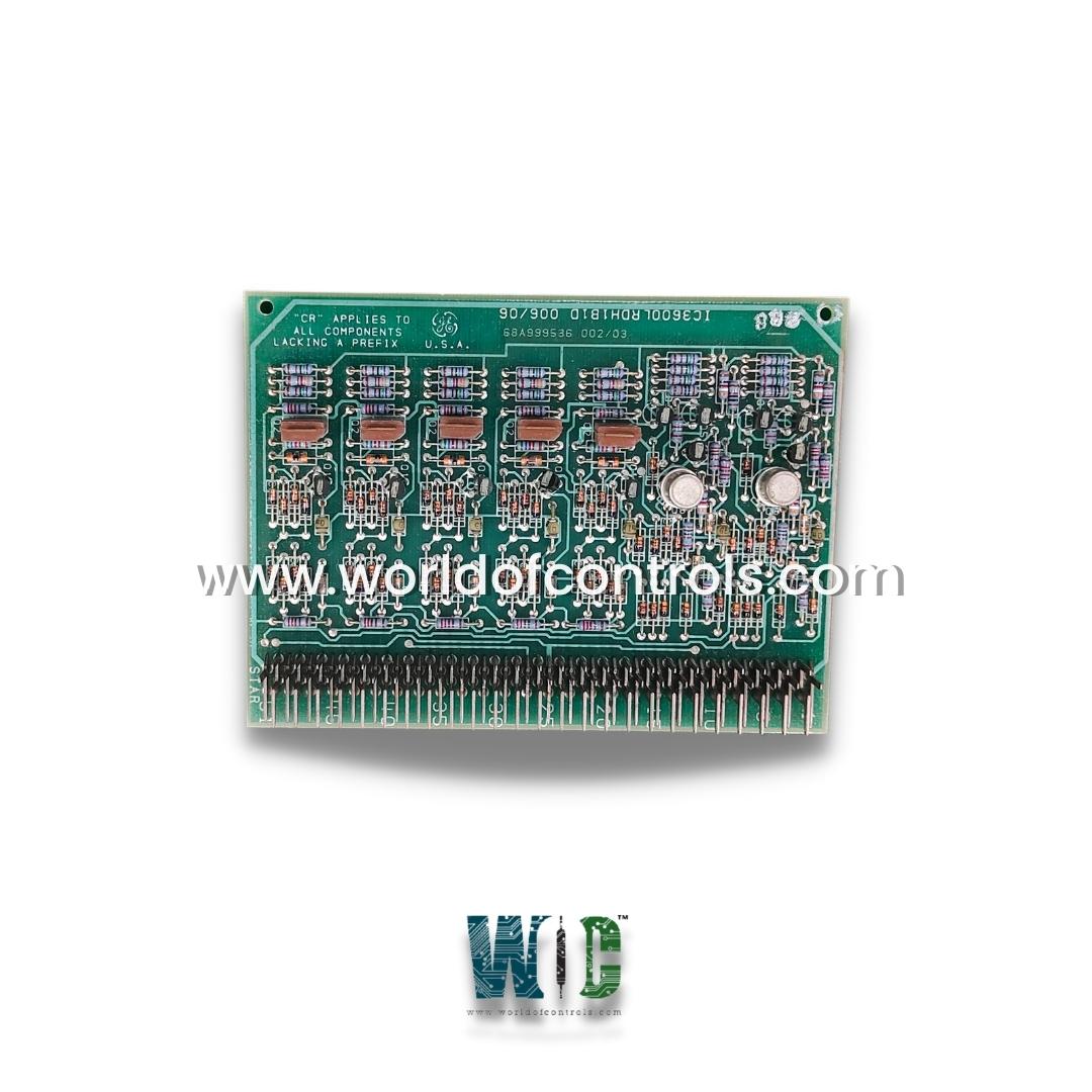
World Of Controls understands the criticality of your requirement and works towards reducing the lead time as much as possible.
IC3600LRDH1B1D - Relay Driver Circuit Board is available in stock which ships the same day.
IC3600LRDH1B1D - Relay Driver Circuit Board comes in UNUSED as well as REBUILT condition.
To avail our best deals for IC3600LRDH1B1D - Relay Driver Circuit Board, contact us and we will get back to you within 24 hours.
Part No: IC3600LRDH1B1D
Manufacturer: General Electric
Function: Relay Driver Circuit Board
Series: Mark I and II
Repair: 3-7 Day
Availability: In Stock
Country of Manufacturer: United States (USA)
IC3600LRDH1B1D is a Relay Driver Circuit Board developed by GE. It is a part of Mark I and II control system. The Relay Driver Circuit Board is designed to control and manage the activation of relays in these control systems. It is a link between the control logic and the actuation of electrical relays, making it an integral part of ensuring the correct operation of the system.
WOC is happy to assist you with any of your GE requirements. Please contact us by phone or email for pricing and availability on any parts and repairs.
What is IC3600LRDH1B1D?
It is a Relay Driver Circuit Board developed by GE
How do Circuits 6 and 7 differ from Circuits 1 through 5?
Circuits 6 and 7 have a similar operation but with a slight variation. Instead of a 2-input gate, they use a 3-input AND gate. When closure to common is established in Circuits 6 and 7, they generate a logic 0 at the output. In these circuits, a logic 0 is produced when the input conditions are met to close the circuit to common.
What is the purpose of diode suppression in these circuits?
Diode suppression is integrated into the circuit card to ensure smooth and reliable operation. It prevents unwanted voltage spikes and transients, which can be harmful to the components and system. The suppression feature helps maintain the integrity and stability of the circuits.
Is diode suppression required on the relay?
No, diode suppression is not required on the relay. It is specifically incorporated into the circuit card to protect the components and maintain proper functioning, and it is not necessary on the relay itself.