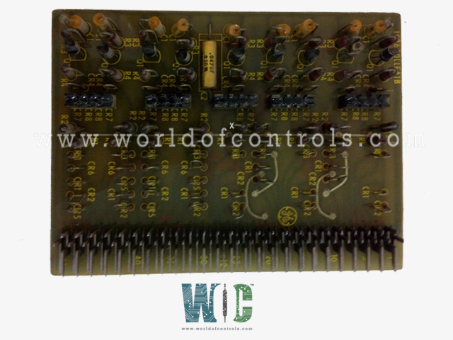
World Of Controls understands the criticality of your requirement and works towards reducing the lead time as much as possible.
IC3600LLEA1C - Logic Inverter Circiut Board is available in stock which ships the same day.
IC3600LLEA1C - Logic Inverter Circiut Board comes in UNUSED as well as REBUILT condition.
To avail our best deals for IC3600LLEA1C - Logic Inverter Circiut Board, contact us and we will get back to you within 24 hours.
Part No: IC3600LLEA1C
Manufacturer: General Electric
Function: Logic Inverter Circuit Board
Series: Mark I and II
Repair: 3-7 Day
Availability: In Stock
Country of Manufacturer: United States (USA)
IC3600LLEA1C is a logic inverter circuit board developed by GE. It is a part of Mark I and II control systems. The logic inverter circuit board plays a vital role in these control systems, facilitating the efficient and precise control of various processes and machinery. By inverting logic signals, it ensures the correct operation of devices and machinery connected to the system, contributing to the overall reliability and safety of the controlled processes.
WOC is happy to assist you with any of your GE requirements. Please contact us by phone or email for pricing and availability on any parts and repairs.
What is IC3600LLEA1C?
It is a Logic Inverter Circiut Board developed by GE
How is the logic level specified for the active condition of the inputs?
The logic level for the active condition is specified and defined through the output signal nomenclature. This nomenclature provides a standardized way to indicate the state of the inputs.
What is the significance of an illuminated LED?
An illuminated LED is typically used to denote the active condition of inputs. When the LED is on, it signifies this state. The symbol mentioned earlier is used to represent this condition, and the output is labeled as X.
How does the choice of symbol relate to the operation of a relay in the LLEA system?
When the active condition involves the energization of a relay, a different symbol is used. If 1 is desired at the OUT to indicate the active condition and the activation of the relay, the same symbol, as previously described, is used, and the output is labeled X. The choice of symbol is directly tied to the desired logic level and its connection to the relay operation.