SPECIFICATIONS
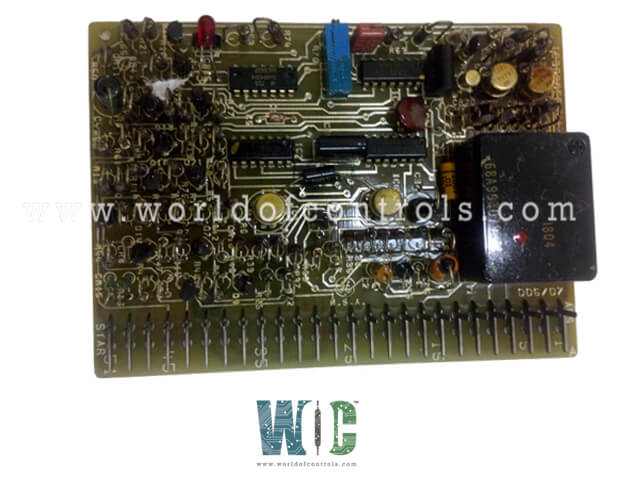
Part No.: IC3600EPSU1J
Manufacturer: General Electric
Country of Manufacture: United States of America (USA)
Product Type: PS VR1 Inverter Card
Availability: In Stock
Series: VersaMax
Functional Description
IC3600EPSU1J is a PS VR1 Inverter Card. It is designed for use in applications requiring efficient control of power inversion. This card is specifically connected to the primary side of a time ratio controlled transistor inverter, which plays a crucial role in managing the conversion of direct current (DC) to alternating current (AC).
Importance of Time Ratio Control
- Time ratio control is a vital function of the inverter card, particularly because the input open-circuit (OC) voltage can fluctuate between 95 and 150 volts.
- This variation necessitates precise control to ensure the inverter operates effectively without exceeding its designed parameters. The EPSU1J card facilitates this control by managing the switching process between the A and B sides of the inverter. Additionally, it includes a built-in current limit circuit that helps shut down the inverter when it reaches saturation, preventing potential damage from overcurrent situations.
Operation and Functionality
- The inverter is activated by pulse signals generated from the secondary control card. This secondary card is responsible for regulating voltage on one of the secondary windings of the inverter.
- The pulse rate generated is between 700 to 800 pulses per second, which translates to a frequency of 350 to 400 Hz on the power inverter. This precise pulse modulation is critical for maintaining the desired output characteristics of the inverter.
Components
- Power Supply: The power supply section is responsible for providing the necessary DC voltage to the inverter card. DC is applied through an external resistor and Zener diode to several components, including PS1, Q1, Q2, and T1, forming a 60 kHz inverter. The center-tapped secondary of this inverter is rectified to generate the PS, NS, and PS buses essential for the card’s operation. Additionally, an isolated winding supplies limited power for critical logic functions on the secondary side of the power inverter.
- Current Limit: This component ensures that the inverter does not exceed its current ratings. Connections to external power transistors and their corresponding load-sharing/current limit resistors (R33-R35) are critical here. These resistors apply the average voltage to the inverting input of the current limit amplifier (CLA). The current limit potentiometer sets a reference voltage on the normal side between 1.2 to 1.9 volts. The CLA consists of a differential amplifier driving a transistor switch, which monitors and regulates current flow.
- Sequencing: The sequencing section orchestrates the operation of the inverter, ensuring that all components function in a coordinated manner. This prevents misalignment in the timing of the switching process and enhances overall reliability.
- Base Drive: The base drive component is essential for controlling the switching transistors that manage the power inversion process. It provides the necessary drive signals to ensure that the transistors operate efficiently.
- Protective Circuitry: Protection mechanisms are integrated into the inverter card to guard against conditions that could lead to failure or unsafe operation. This includes safeguards against excessive current and voltage, as well as thermal overload conditions.
Monitoring and Diagnostics
It includes provisions for monitoring its performance through outputs that can be connected to an oscilloscope. Specifically, points IA and IB are provided for this purpose, allowing for real-time observation of current waveforms and operational integrity.
The WOC team is always available to help you with your Mark I and II requirements. For more information, please contact WOC.
Frequently Asked Questions
What is IC3600EPSU1J?
It is a PS VR1 Inverter Card developed by GE under the VersaMax series.
Why is time ratio control necessary for this inverter card?
Time ratio control is essential because the input open-circuit voltage can vary from 95 to 150 volts. This variability requires precise management to ensure the inverter operates effectively without exceeding its operational limits, thereby preventing potential damage.
How does the component control switching in the inverter?
The card manages the switching between the A and B sides of the inverter through a current limit circuit. It receives pulses from the secondary control card (EPSV), which regulates the voltage on one of the secondary windings, activating the inverter at pulse rates of 700 to 800 pulses per second (350 to 400 Hz).
How does the current limit function work?
The current limit function monitors the average voltage applied to the inverting input of the current limit amplifier (CLA). If the monitored voltage exceeds a set threshold, it triggers a shutdown mechanism to prevent the inverter from entering an overcurrent state, ensuring safe operation.
