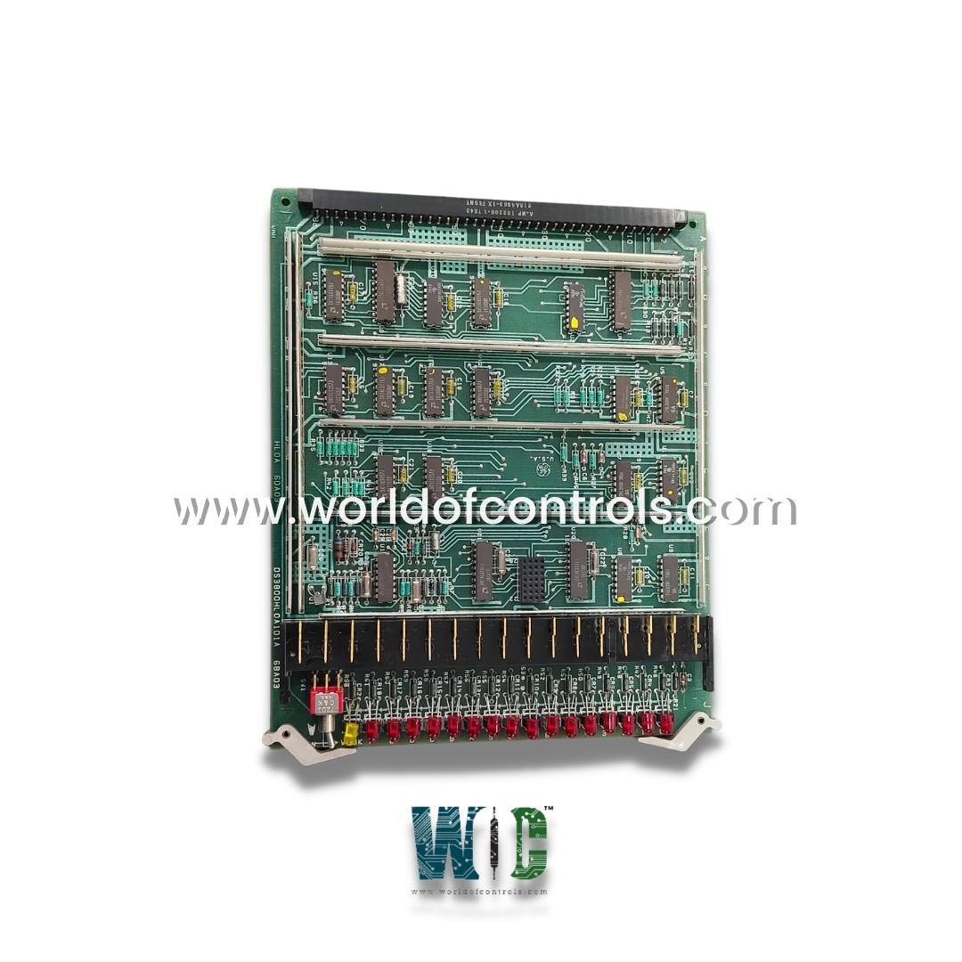
World Of Controls understands the criticality of your requirement and works towards reducing the lead time as much as possible.
DS3800HLOA1D1A - Logic Driver Bus Interface Board is available in stock which ships the same day.
DS3800HLOA1D1A - Logic Driver Bus Interface Board comes in UNUSED as well as REBUILT condition.
To avail our best deals for DS3800HLOA1D1A - Logic Driver Bus Interface Board, contact us and we will get back to you within 24 hours.
SPECIFICATIONS:
Part Number: DS3800HLOA1D1A
Manufacturer: General Electric
Series: Mark IV
Product Type: Logic Driver Bus Interface Board
Signal Types: Analog signals
Number of channels: 12
Analog-to-Digital Conversion: 12-bit
Input Impedance: 10k - 100k Ohm
Operating Voltage: 5V, 12V, 24V
Current Measurement Range: 0-100A
Voltage Measurement Range: 0-250V
Signal Input Range: 0-10V
Operating temperature: -40 to 85 degrees Celsius
Response Time: 1-10ms
Size: 8.25 cm high x 4.18 cm
Repair: 3-7 Day
Availability: In Stock
Weight: 2 lbs
Country of Origin: United States
FUNCTIONAL DESCRIPTION:
DS3800HLOA1D1A is a Logic Driver Bus Interface Board manufactured and designed by General Electric as part of the Mark IV Series used in GE Speedtronic Gas Turbine Control Systems. A Logic Driver Bus Interface Board serves as an essential component in modern electronic systems, particularly where communication and coordination between various subsystems are necessary. Its primary role is to act as an intermediary between a central processing unit (CPU) or microcontroller and a bus system, which is responsible for transferring data to and from multiple devices. The board facilitates the seamless exchange of data by converting and managing signals, ensuring proper communication between components that may operate at different voltage or logic levels.
One of the key functions of a Logic Driver Bus Interface Board is signal conversion. Often, the devices connected to the bus operate at different voltage levels or use different communication protocols. The board helps translate these signals to a standard format that the central processor or other components can understand, enabling smooth communication. For instance, it might convert a 3.3V logic signal to a 5V signal, allowing components with differing voltage tolerances to communicate effectively.
FUNCTIONAL OF LOGIC DRIVER BUS INTERFACE BOARD:
WOC maintains the largest inventory of Replacement parts for GE Speedtronic control systems. Additionally, we offer warranty-backed unused and rebuilt boards as well as board repairs for damaged ones. Our team of professionals is available around the clock for your OEM needs. We at WOC are happy to help you with any automation needs you may have. Please get in touch with our team by phone or email for pricing and availability on any components and repairs.
What is a Logic Driver Bus Interface Board?
A Logic Driver Bus Interface Board is a component used to facilitate communication between a central processing unit (CPU) or microcontroller and other devices in a system, typically through a bus. It manages signal conversion, data transfer, and control signals between devices that may operate at different logic levels or communication protocols.
What is the role of signal conversion in a Logic Driver Bus Interface Board?
Signal conversion is one of the key functions of this board. It allows devices that operate at different voltage or logic levels (e.g., 3.3V, 5V, etc.) to communicate by converting the signals to a common format compatible with the entire system.
What types of communication protocols are supported by Logic Driver Bus Interface Boards?
Logic Driver Bus Interface Boards can support multiple communication protocols, such as I2C, SPI, CAN, and UART, depending on the system’s requirements. These protocols allow different devices to exchange data using standard communication formats.