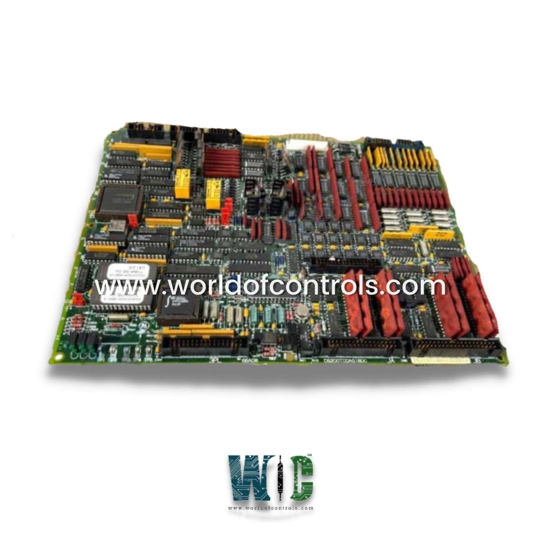
World Of Controls understands the criticality of your requirement and works towards reducing the lead time as much as possible.
DS215TCQAG1BZZ01A - Analog I/O Board is available in stock which ships the same day.
DS215TCQAG1BZZ01A - Analog I/O Board comes in UNUSED as well as REBUILT condition.
To avail our best deals for DS215TCQAG1BZZ01A - Analog I/O Board, contact us and we will get back to you within 24 hours.
SPECIFICATIONS
Part Number: DS215TCQAG1BZZ01A
Manufacturer: General Electric
Series: Mark V LM
Product Type: I/O Board
Availability: In Stock
Country/Region of Manufacture: United States
Repair: 3-7 Days
Manual: GEH-6153
DS215TCQAG1BZZ01A is an Analog I/O Board manufactured and designed by General Electric as part of the Mark V LM Series used in turbine control systems. The Analog IO Board (TCQA) scales and conditions a large number of the analog signals that terminal boards mounted on the I/O cores R1, R2, and R3 read in. Included in this group of signals are the LVDT inputs, servo valve outputs, thermocouple inputs, 4-20 mA inputs and outputs, vibration inputs, relay driver outputs, pulse inputs, voltage inputs, and generator and line signals. On the STCA board, some of the signals are written via the 3PL connector. Through the JE connector, the TCQC board receives and transmits generator and line signals. The TCQA board scales and conditions input signals that are 420 mA, including the fuel flow pressure and compressor stall-detect signals.
TCQA CONNECTORS:
2PL - Distributes electricity to the, and cores from the TCPS board.
3PL - The Data Bus between the STCA, TCQA, and TCQE boards in the cores as well as between the STCA, TCQA, and TCQE boards in the core. For transmission to the COREBUS, conditionally conditioned signals are conveyed on 3PL.
JA - Carries the thermocouple inputs and cold junction correction for the corresponding R1, R2, and R3 cores from the TBQA board connection JAR/S/T.
JB - Carries the inputs and outputs for 4-20 mA to and from the JBR terminal board connection on the TBQC.
JD - Transports trip signals from the R1 core to the TCTG board in the P1 core; not utilized in R2 or R3.
TCQA CONFIGURATION:
HARDWARE: The mA output circuits are chosen using hardware jumpers J1 and J2. The mA outputs current range, either 20 mA maximum or 200 mA maximum, is configured using J5 and J6. For card tests, the RS232 port is connected to J7. An oscillator is activated by J8. For details on the hardware jumper settings for this board, consult Appendix A and the operator interface's hardware jumper panel.
SOFTWARE: The following describes how to enter I/O Configuration constants for the 4-20 mA inputs and outputs, vibrations, LVDT locations, pulse rates, and thermocouples in the I/O Configuration Editor on the operator interface.
PULSE RATE INPUT CIRCUIT:
The TCQA board houses the circuitry that scales and conditions the pulse rate inputs read from the TCQC board through the JE connector. These signals come from the magnetic pick-up inputs and TTL (transistor to transistor logic) inputs, whose signals are sent to the QTBA and/or PTBA terminal boards. The inputs for the high-pressure shaft speed go to the "R1" core. Additional signals may be used with the pulse rate input circuits on R2 and R3.
TCQA 4-20 mA INPUT CIRCUITS:
The circuitry for the 0-1 mA and 4-20 mA input signals is provided by the TCQA board. Through the JB connector, the signals are read from the TBQC terminal board. The voltage drop is measured by the TCQA board and written to the I/O Engine via the 3PL connector as the transducer current is reduced across a burden resistor. The current range of the input signals is chosen using hardware jumpers on the TBQC terminal board.
TCQA 4-20 mA OUTPUT CIRCUITS:
The circuitry for driving 4-20 mA outputs to the TBQC terminal board through the JB connector is provided by the TCQA board. Usually, these signals are utilized to power control equipment.
TCQA THERMOCOUPLE CIRCUIT:
The TBQA terminal board is coupled to thermocouples. The thermocouple cold junction reference, which is used by TCQA to compute the cold junction compensation, is provided by circuits that are likewise housed on the TBQA terminal board. The actual temperature read by the thermocouple is determined by the TCQA board using the thermocouple input and compensation setting. Via the 3PL connector, the I/O Engine reads the value. I/O configuration constants are used to select the types and curves of thermocouples.
WOC has the largest stock of GE Speedtronic Mark V LM Replacement Parts. We can also repair your faulty boards. WORLD OF CONTROLS can also supply unused and rebuilt backed up with a warranty. Our team of experts is available round the clock to support your OEM needs. Our team of experts atWOC is happy to assist you with any of your automation requirements. For pricing and availability on any parts and repairs, kindly get in touch with our team by phone or email.
FREQUENTLY ASKED QUESTIONS
Which input formats can the DS215TCQAG1BZZ01A read?
LVDT inputs are read by TCQA. A dedicated ribbon wire connects the analog input output board in the R control processor to the first redundant transducer input for VDC1 and VDC2.
What regulators are included in the software of the TCQA?
The input-output setup software on TCQA in each control processor in the Mark V includes digital control regulators.
How to Check Price and Availability For DS215TCQAG1BZZ01A?
Please Contact World of Controls FZE for sales at +1 609 385 1231 or Request a Quote.