SPECIFICATIONS
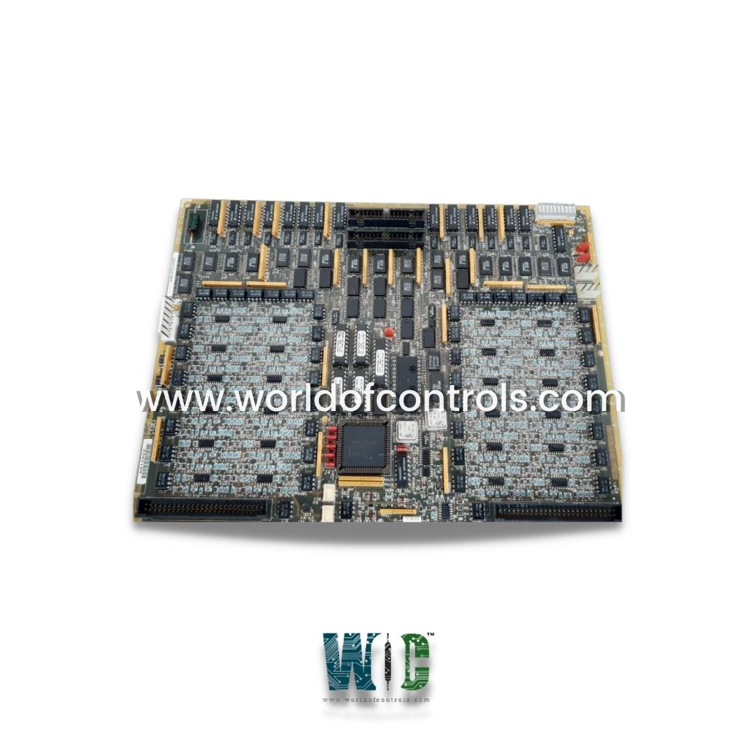
Part Number: DS215TCDAG1BZZ01A
Manufacturer: General Electric
Series: Mark V
Manual: GEH-6195
Product type: Board with Firmware
Function: I/O Board
Country of Manufacture: United States (USA)
Functional Description
DS215TCDAG1BZZ01A is an I/O Board with Firmware developed by GE. It is a part of mark V control system. If present, the Digital IO Board is located in the digital I/O cores Q11, Q51, and Q21. The board is responsible for processing digital contact input signals from the DTBA and DTBB terminal boards, as well as contact output (relay/solenoid) signals from the two boards. The signals are routed through the IONET to the TCQC board in R1, R2 if Q21 is present, and the CTBA terminal board in R5.
Connectors
- JP Connector: The JP connector serves as a power distribution channel within the system. Originating from the TCPS board, this connector carries power to the Q11, Q21, and Q51 cores. It accomplishes this task by routing power via the R1, R2, and R5 cores. By effectively distributing power, the JP connector ensures that the designated cores receive the necessary electrical supply to function optimally.
- JQ Connector: The JQ connector establishes a link between the DTBA board's JQR socket and the I/O boards. It serves as a conduit for transporting contact input signals from the DTBA to the boards. This communication pathway enables the TCDA boards to receive and process input signals generated by the DTBA, facilitating critical interactions and responses within the system.
- JR Connector: Similar to the JQ connector, the JR connector connects the DTBB board's JRR socket to the I/O boards. It functions as a conduit for transmitting contact input signals from the DTBB to the boards. By establishing this connection, the system enables seamless data transfer between the DTBB and the I/O boards, enhancing the system's ability to monitor and respond to input signals.
- JO1 and JO2 Connectors: JO1 and JO2 connectors are responsible for sending contact output signals, often associated with relays or solenoids, to the TCRA board. JO1 transmits these signals to the TCRA board located in position four, while JO2 accomplishes the same task for the board in location five. Notably, the relays in position four are controlled directly by TCQE in R1 and are not utilized in Q11. These connectors enable precise control over output signals, contributing to the overall functionality of the system.
- JX1 and JX2 Connectors: JX1 and JX2 connectors are part of a shielded twisted pair used for IONET signals. These connectors play a key role in data transmission between different components. Specifically, the module in the Q11 core writes signals to the JX2 connection on the TCEA board located in position five of the P1 core. Similarly, the board in the Q51 core writes signals to the JX connection on the CTBA in the R5 core. This communication mechanism allows for the exchange of critical signals and data, contributing to the coordination and operation of the entire system.
Configuration
- Hardware - The TCDA board has eight hardware jumpers. J1 and J8 are used for factory testing. J2 and J3 are used to connect IONET termination resistors. J4, J5, and J6 are used to configure the board's IONET ID. J7 controls the stall timer. For information on the hardware jumper settings for this board, see Appendix A and the hardware jumper screen on the operator interface. Software. I/O configuration constants for contact input inversions are entered in the HMI's I/O Configuration Editor.
- Software - SDCC contains the primary control circuits and software for the drive. The board also includes general-purpose interface circuits that connect to other boards to form different types of ac and do motor drives. Drive and motor signals, as well as customer I/O, are controlled and processed by the interface circuits.
Contact Input Circuits
- Contact inputs from the DTBA and DTBB terminal boards are routed to the TCDA board via the JR and JQ connectors.
- The board's circuitry conditions the signals, timestamps any changes in state, and sends them to the IONET via the JX1 (JX2) connector. Contact signal inversions are performed using software and I/O configuration constants.
WOC is happy to assist you with any of your automation requirements. Please contact us by phone or email for pricing and availability on any parts and repairs.
FREQUENTLY ASKED QUESTIONS
What is DS215TCDAG1BZZ01A?
It is an I/O Board with Firmware developed by GE.
What are digital contact input signals?
Digital contact input signals are electrical signals that indicate the presence or absence of a voltage or current on an input channel. These signals are used to detect the state of digital input devices such as switches, push-buttons, and sensors.
What are contact output signals?
Contact output signals are electrical signals that control the state of output devices such as relays and solenoids. When a signal is received, the output device is either turned on or off, depending on the state of the signal.
What is the IONET?
The IONET is a network that connects the different boards and modules in a control system. It allows signals and data to be exchanged between different parts of the system, enabling them to work together to perform a specific function.
What is the CTBA terminal board?
The CTBA terminal board is a board located in R5 that provides connections for field devices such as sensors, switches, and relays. It allows these devices to be connected to the control system and communicate with the TCDA board and other parts of the system.
