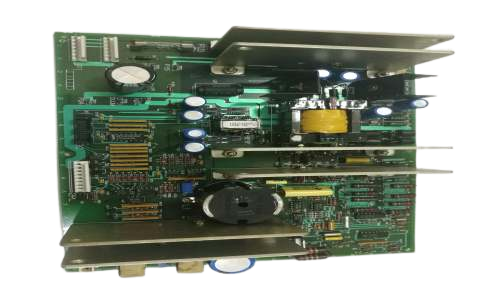
World Of Controls understands the criticality of your requirement and works towards reducing the lead time as much as possible.
DS215TCCAG1BZZ01A - Common Analog I/O Board is available in stock which ships the same day.
DS215TCCAG1BZZ01A - Common Analog I/O Board comes in UNUSED as well as REBUILT condition.
To avail our best deals for DS215TCCAG1BZZ01A - Common Analog I/O Board, contact us and we will get back to you within 24 hours.
SPECIFICATIONS:
Part Number: DS215TCCAG1BZZ01A
Manufacturer: General Electric
Series: Mark V
Product Type: Terminal Board
Input Channels: 8 Analog Inputs
Input Resolution: 12-bit / 16-bit
Output Type: Voltage (0-10V, ±10V)
Output Resolution: 12-bit / 16-bit
Input Type: Voltage (0-10V, ±10V)
Communication Protocol: RS-485
Power Supply: 24V DC ±10%, < 5W
Isolation: 1500V
Mounting Options: DIN Rail
Operating Temperature: -20°C to 70°C
Country/Region of Manufacture: United States
Availability: In Stock
FUNCTIONAL DESCRIPTION:
DS215TCCAG1BZZ01A is a Common Analog I/O Board manufactured and Designed by General Electric as part of the Mark V Series used in gas turbine control systems. The Common Analog I/O Board (TCCA) in the
TCCA CONNECTORS:
TCCA CONFIGURATION:
Hardware: There are three hardware jumpers - J1, JP2, and JP3 on the TCCA board. J1 is used to enable/disable the serial RS232 port. JP2 is used to disable the oscillator for the card test. JP3 is used for factory tests.
Software: I/O configuration constants for the thermocouples, RTDs, mA inputs and outputs, and the shaft voltage and current settings are entered in the I/O Configuration Editor located on the HMI as described below.
TCCA 4 - 20 mA INPUT CIRCUIT:
The TCCA board processes 4-20 mA input signals from the CTBA terminal board via the JBB connector. The transducer current is dropped across a burden resistor, and the resulting voltage drop is read by the TCCA board and transmitted to the I/O Engine through the 3PL connector.
TCCA 4 - 20 mA INPUT CIRCUIT:
The TCCA board provides the circuitry for driving 4-20 mA outputs to the CTBA terminal board via the JAA connector. These signals are typically used to drive remote instrumentation for monitoring.
SHAFT MONITORING:
The TCCA board monitors voltage and current for the turbine shaft, receiving signals from the CTBA terminal board via the JBB connector and transmitting them to the I/O Engine through the 3PL connector. Located in R5 core location 2, the TCCA board, also known as the Turbine Control
WOC has the largest stock of GE Speedtronic Control System Replacement Parts. We can also supply unused and rebuilt backed-up with a warranty. Our team of experts is available round the clock to support your OEM needs. Our team of experts at WOC is happy to assist you with any of your automation requirements. For pricing and availability on any parts and repairs, kindly contact our team by phone or email.
What is the function of the TCCA board?
The TCCA (Common Analog I/O) board conditions and processes analog signals from various terminal boards in the
How does the TCCA board process 4-20 mA signals?
4-20 mA signals are received from the CTBA terminal board via the JBB connector. The transducer current is dropped across a burden resistor, and the resulting voltage drop is read by the TCCA board and sent to the I/O Engine through the 3PL connector.
What is the function of the 3PL connector?
The 3PL connector serves as the data bus between the TCCA, STCA, and TCCB boards in the R5 core. It is responsible for transmitting conditioned signals from the TCCA to the COREBUS, ensuring seamless communication and data exchange within the turbine control system.