SPECIFICATIONS
Part No.: DS215SDCCG4A
Manufacturer: General Electric
Country of Manufacture: United States of America (USA)
Temperature: -30 to + 65oC
Product Type: Drive Control Card
Availability: In Stock
Series: Mark V
Functional Description
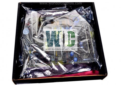
DS215SDCCG4A is an Drive Control Card developed by GE. It is a part of Mark V control system. It is a primary control system for a drive or exciter, providing essential circuitry and software functionality. It consists of three 16-bit microprocessors, which form the core processing units of the control system. These microprocessors handle various tasks related to control, monitoring, and data processing within the drive or exciter system.
Features
- Dual-Ported RAM (DPR): It utilizes Dual-Ported RAM (DPR) as part of its memory architecture. DPR is a type of RAM configured as memory arrays that can be independently and simultaneously accessed by two microprocessors. This allows for efficient data exchange and synchronization between the microprocessors.
- Functionality and Software: Responsible for executing control algorithms, managing system parameters, and coordinating the operation of the drive or exciter. It runs specialized software tailored to the specific requirements of the application, ensuring smooth and reliable operation of the system.
- Interprocessor Communication: Interprocessor communication is facilitated through the dual-ported RAM, enabling seamless exchange of data and instructions between the three microprocessors. This communication mechanism ensures coordinated operation and synchronization of tasks.
Testpoints
- Testpoints serve as convenient access points within the SDCC circuitry, allowing engineers and technicians to monitor, measure, or probe specific signals during testing and troubleshooting procedures. By providing access to critical signal paths, testpoints enable efficient diagnosis of system issues and verification of proper operation.
- Testpoints are typically metal posts strategically located within the SDCC circuitry, along specific signal paths of interest. These posts are designed to accommodate test probes or clips, making it easy to connect measuring instruments such as oscilloscopes, multimeters, or logic analyzers for signal analysis.
- During testing and troubleshooting activities, engineers can use testpoints to observe various signals in real-time, assess signal integrity, measure voltage levels, monitor waveforms, and analyze system behavior. This enables the identification of potential faults, anomalies, or performance issues within the SDCC.
Configurable Hardware
- Berg-type hardware jumpers are manually movable components used to configure certain aspects of the SDCC for specific applications. These jumpers are identified by a JP nomenclature and are typically found on the circuit board. By adjusting the positions of these jumpers, users can select various options or settings, such as enabling or disabling certain features, configuring communication protocols, or adjusting signal paths.
- Wire jumpers, identified by a WJ nomenclature, are another type of configurable hardware component present in the SDCC. These jumpers consist of wires that are used to establish connections or bridges between different points on the circuit board. Similar to Berg-type jumpers, wire jumpers allow users to customize the configuration of the SDCC to suit specific requirements or preferences. They may be used for factory tests or to provide user application options.
- It is essential to set the configurable hardware elements correctly to ensure proper operation and compatibility with the intended application. Incorrect jumper settings can lead to system malfunctions, erratic behavior, or compatibility issues. Therefore, users must refer to the documentation provided with the SDCC, including test data sheets supplied with each controller, to identify the factory-set positions of the jumpers and ensure that any adjustments made align with the recommended configurations.
- Most of the jumper selections in the SDCC are factory-set to predefined configurations based on common application scenarios or default settings. The test data sheets supplied with each controller, typically stored in the drive/exciter door pocket, contain detailed information regarding these factory-set positions. Users can refer to these documents to understand the initial jumper configurations and make informed decisions when adjusting the jumpers for their specific requirements.
The WOC team is always available to help you with your Mark V requirements. For more information, please contact WOC.
Frequently Asked Questions
What is DS215SDCCG4A?
It is a drive control card developed by GE under the Mark V series.
What are Berg-type hardware jumpers, and how are they identified?
Berg-type hardware jumpers are manually movable components used for configuration purposes. They are identified by a JP nomenclature and are typically found on the circuit board. These jumpers allow users to select various options or settings by adjusting their positions.
What are wire jumpers, and how are they identified?
Wire jumpers, identified by a WJ nomenclature, are wires used to establish connections or bridges between different points on the circuit board of the SDCC. They serve similar purposes to Berg-type jumpers and provide users with flexibility in configuring the system for specific requirements or preferences.
How can I ensure that I set the configurable hardware correctly?
To ensure the correct configuration of the configurable hardware, users should refer to the documentation provided with the system. This documentation includes test data sheets supplied with each controller, typically stored in the drive/exciter door pocket. These sheets contain detailed information about the factory-set positions of the jumpers and provide guidance on making adjustments for specific applications.
