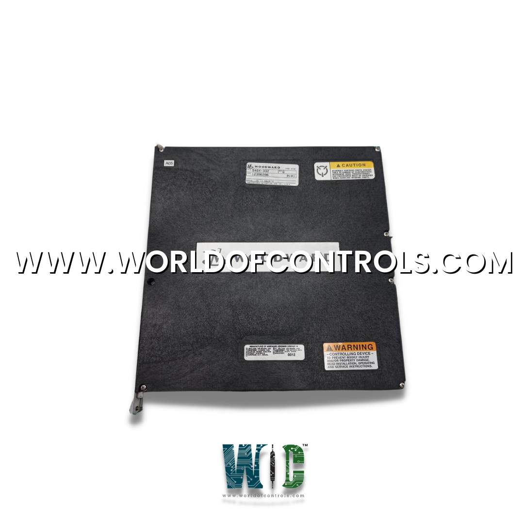
SPECIFICATIONS
Part Number: 5464-332
Manufacturer: Woodward
Product type: Analog Input Module
Temp drift: 275 ppm/C, maximum
Fuse: 100 mA fuse per channel
Anti-aliasing filter: 2 poles at 10 ms
Resolution: 16 bits
Availability: In Stock
Country of Manufacture: United States (USA)
Functional Description
5464-332 is an Analog Input Module developed by Woodward. The modules are designed for effortless integration and hassle-free operation, as they come equipped with no potentiometers and require no calibration. The module offers a highly convenient configuration, catering to various input and output needs. It provides a total of 24 channels for 4-20 mA inputs, allowing precise monitoring and control of multiple signals. Additionally, the module offers 8 channels of 4-20 mA outputs, facilitating seamless control over external devices or processes. To ensure accurate and reliable data acquisition, the input channels are equipped with a 2-pole 10 ms filter, effectively eliminating unwanted noise and fluctuations from the input signals. For channels 23 and 24, a slightly faster 2-pole 5 ms filter is applied, optimizing the response time for these specific channels.
Features
- Number of Channels: The module supports 8 output channels, allowing control and modulation of various devices or processes.
- Update Time: The module's update time is an impressive 5 milliseconds, enabling rapid and precise adjustments to the output signals.
- Output Driver: The module utilizes a Pulse Width Modulated (PWM) output driver, offering efficient control over the output signals.
- PWM Frequency: The PWM frequency is set at 6.14 kHz, allowing for high-speed and accurate pulse modulation.
- Filter: The module incorporates a 3-pole filter with a time constant of 500 milliseconds, ensuring smooth and stable output signals.
- Current Output: The output signals are in the form of current, with a range of 4-20 mA, providing flexibility and compatibility with various devices.
- Current Output Range: The current output range can be adjusted between 0 and 25 mA, offering versatility in signal intensity.
- Isolation: The module boasts complete isolation with 0 Vrms, ensuring enhanced safety and reducing the risk of signal interference.
- Max Load Resistance: The module can handle a maximum load resistance of 600 ohms, which includes both the load and wire resistance, providing flexibility in the choice of connected devices.
- Current Readback: The module utilizes an 8-bit current readback system, allowing for accurate monitoring and feedback of the output currents.
- Readback Isolation: The readback system provides a high level of isolation, with 60 dB common-mode rejection ratio (CMRR) and 200 Vdc common mode rejection, reducing noise and interference.
- Voltage Specifications:
- Resolution: The voltage output of the module offers a high resolution of 11 bits, ensuring precise control and adjustment of voltage signals.
- Accuracy: The module's voltage output is software-calibrated to achieve an impressive accuracy of 0.2% within the 0-25 mA full-scale range, delivering precise and reliable voltage signals.
- Temperature Drift: With a maximum temperature drift of 125 ppm/C, the module ensures stability in output signals even in varying temperature conditions.
- Readback Accuracy: The readback system provides an accuracy of 0.5% within the 0-25 mA full-scale range, enabling accurate monitoring and feedback.
- Readback Temperature Drift: The maximum readback temperature drift is 400 ppm/C, ensuring consistent and reliable readback data even in changing temperatures.
Installation
- The installation and configuration of the modules within the control's chassis are designed to be efficient and user-friendly. The modules are carefully designed to slide easily into the card guides, aligning perfectly with the motherboard's connectors. Once in position, the modules are securely held in place by two screws located at the top and bottom of the front panel, ensuring a stable and reliable connection.
- To facilitate easy maintenance and module removal, the modules are equipped with two handles, one at the top and another at the bottom. By toggling these handles outward, the modules can be moved slightly outward, allowing the circuit boards to disengage from the motherboard connectors. This feature simplifies the process of removing and replacing modules during maintenance or upgrades, reducing downtime and streamlining the overall operation.
- These modules are connected through high-density 62-conductor analog cables, with each module requiring two cables (one for each sub D connector on the front panel).
- Equipped with two sub-D connectors on its front panel. The top sub D connector contains the first half of the analog channels, encompassing analog input channels 1 to 12 and analog output channels 1 to 4. Similarly, the bottom sub-D connector houses the second half of the I/O channels, including the remaining analog input and output channels.
- The front panel layout and organization of the sub D connectors make it straightforward to identify and configure the various analog channels, simplifying the setup and troubleshooting processes for users.
- This thoughtful and well-designed module and cabling configuration ensures seamless integration of the 24/8 Analog I/O modules into the control system. The combination of secure module placement, easy handling through the handles, and organized channel arrangements ensures the control system operates efficiently and accurately, meeting the diverse analog input and output needs of industrial applications.
World of Controls has the most comprehensive selection of GE and Woodward components. Our professionals are available to help you with your requirements at any time. If you require any additional information, please contact WOC immediately.
Frequently Asked Questions
What is 5464-332?
It is an Analog Input Module developed by Woodward.
Does the module offer isolation for enhanced safety?
Yes, the module boasts complete isolation with 0 Vrms, ensuring enhanced safety and minimizing the risk of signal interference.
What is the maximum load resistance that the module can handle?
The module is capable of handling a maximum load resistance of 600 ohms, encompassing both the load and wire resistance. This provides flexibility in selecting compatible devices.
How is the current output monitored and controlled?
The module utilizes an 8-bit current readback system, allowing for accurate monitoring and feedback of the output currents.
